Система акумуляторного живлення пікапа у автопарку відрізняється від системи в окремому позашляховику 4×4. У випадку з одним автомобілем монтажник може вирішувати проблеми, покладаючись на власний досвід. У автопарку це стає ризиком. Якщо в кожному пікапі прокладка кабелів, розташування запобіжників, стиль маркування та положення акумулятора відрізняються, керівник автопарку зрештою поплатить за це через простої, повільну діагностику несправностей, суперечки щодо гарантії та небезпечні роботи з технічного обслуговування.
Саме тому виробники пікапів для автопарків, виробники тентів та фахівці з монтажу автоелектрообладнання потребують стандарту, що забезпечує стабільне допоміжне живлення. A тонка літієва батарея Це зручно, оскільки вона поміщається у вузькі проміжки під навісом, порожнини в бічних стінках, системи висувних ящиків або лотки, не займаючи стільки місця, скільки займають багато традиційних акумуляторів. Але сам по собі акумулятор ще не робить систему професійною.
Для автомобілів автопарку головна мета — це уніфікація. Кожен пікап має бути простим у збірці, огляді, ремонті та модернізації з використанням єдиної схеми електропроводки, переліку запобіжників, схеми маркування та контрольного списку для введення в експлуатацію.
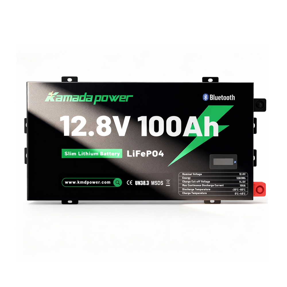
Літієвий акумулятор Kamada Power 12 В, 100 А·год, серії Slimline
Що таке літієва батарея Slimline у комплектації пікапа для автопарку?
A тонка літієва батарея — це компактний допоміжний акумуляторний блок, зазвичай на основі літій-залізо-фосфатних елементів, призначений для встановлення в транспортних засобах з обмеженим простором. У кузові пікапа його зазвичай використовують для живлення робочого освітлення, радіостанцій, невеликих холодильників, обладнання для моніторингу, насосів, зарядних пристроїв для інструментів, USB-роз’ємів та інших 12-вольтних аксесуарів при вимкненому двигуні.
У більшості випадків використання пікапів у автопарках акумулятор типу «slimline» не є стартерним. Він є частиною допоміжної системи живлення, до складу якої можуть входити зарядний пристрій DC-DC, сонячний модуль, головний запобіжник, шина, блок запобіжників, панель перемикачів, роз’єм Андерсона, прилад контролю стану акумулятора та марковані ланцюги навантаження.
Перевага компактної конструкції полягає у свободі планування. Замість того, щоб втрачати площу підлоги в кабіні, акумулятор часто можна встановити на бічній панелі, за сервісною кришкою, усередині висувного модуля або у спеціально відведеному електричному відсіку.
Чому установка акумуляторів у пікапах автопарку має бути стандартизована
Професійність установки на автопарк оцінюється не лише за тим, чи працює перший автомобіль. Вона визначається тим, чи можна таким самим чином виготовити та обслуговувати десятий, п’ятдесятий або двістій автомобіль.
Без стандартизації незначні відмінності перетворюються на серйозні проблеми. У одному пікапі головний запобіжник може бути розташований поруч з акумулятором, а в іншому — прихований за панеллю. Один монтажник може позначати ланцюги за назвою навантаження, а інший — лише за номерами запобіжників. Система може працювати в день поставки, але команда технічного обслуговування зіткнеться з труднощами, коли пізніше виникне несправність.
Стандартизована процедура встановлення акумулятора в пікапі автопарку повинна визначати розташування акумулятора та зарядного пристрою, місця розміщення головного та відгалужених запобіжників, маршрут прокладення кабелів, спосіб заземлення, тип роз’ємів, схему розташування панелі вимикачів, перелік запобіжників, назви ланцюгів, формат маркування, протокол випробувань, фотодокументацію та документ про передачу транспортного засобу.
Належний стандарт експлуатації автопарку не виключає необхідності технічної оцінки. Він забезпечує кожному монтажнику однакову базову основу, завдяки чому кінцева система стає безпечнішою, чистішою та простішою в обслуговуванні.
Вибір місця розміщення акумулятора: на першому місці — зручність доступу
Акумулятори компактної форми часто обирають через те, що в пікапах автопарку місце під кришкою кабіни обмежене. Однак найкраще місце для розміщення не завжди є найприхованішим. У робочих транспортних засобах доступ для технічного обслуговування має бути важливішим за зовнішній вигляд.
Перед тим, як затвердити схему розміщення, монтажники повинні з’ясувати, чи можна перевірити акумулятор без демонтажу важкого обладнання, чи можна швидко дістатися до головного запобіжника або ізолятора, чи залишаються етикетки читабельними після встановлення висувних ящиків та інструментів, а також чи можна зняти акумулятор без демонтажу всього навісу.
Місце монтажу також слід захистити від води, пилу, нагрівання, ударів та вібрації. Для багатьох навісів на пікапах автопарків більш практичним є розміщення електричної панелі на бічній стінці або у захищеному лотку, ніж у глибоко прихованому відсіку. Мета полягає не лише в тому, щоб розмістити акумулятор. Мета полягає в тому, щоб зробити всю електричну систему наочною, логічною та зручною для обслуговування.
Стандартна архітектура електропроводки для пікапів автопарку
Типовий тонка літієва батарея Система для автопарку пікапів може включати стартерний акумулятор, генератор, зарядний пристрій DC-DC, допоміжний літієвий акумулятор, головний запобіжник, мінусову шину, блок запобіжників, панель перемикачів, ланцюги навантаження та опціональний сонячний вхід.
Стандартна архітектура повинна ілюструвати, як енергія протікає через систему:
Джерело заряджання транспортного засобу → зарядний пристрій DC-DC → допоміжний акумулятор → основний захист → розподіл → окремі навантаження з запобіжниками.
Для автопарків схема повинна бути достатньо простою, щоб новий технічний спеціаліст міг її зрозуміти без звернення до фахівця, який виконував монтаж. Кожне основне з’єднання повинно мати позначку, яка відповідає схемі електромонтажу та переліку запобіжників.
Чому зарядні пристрої типу «DC-DC» широко використовуються в пікапах автопарків
Сучасні автомобілі часто характеризуються мінливою роботою генератора, великою довжиною кабельних трас та різними вимогами до заряджання літієвих акумуляторів. Зарядний пристрій типу «постійний струм — постійний струм» (DC-DC) забезпечує контрольоване заряджання допоміжного акумулятора, а також дозволяє спростити стандартизацію для різних моделей пікапів.
Розмір зарядного пристрою слід підбирати з урахуванням допустимого струму зарядки акумулятора, потужності генератора, довжини кабелю, очікуваного часу руху, частки енергії, що надходить від сонячних батарей, та навантаження на додаткове обладнання. Вибір найпотужнішого з доступних зарядних пристроїв не завжди є кращим рішенням. Вибір занадто потужного пристрою може спричинити перегрів, а також проблеми з електропроводкою, запобіжниками та навантаженням на генератор.
Вибір розміру кабелю: стандартизуйте метод, а не покладайтеся на припущення
Правильний підбір перерізу кабелю є одним із найважливіших елементів системи акумуляторного живлення пікапів автопарку. Кабель занадто малого перерізу може спричинити падіння напруги, нагрівання, погіршення ефективності заряджання та ненадійну роботу додаткових пристроїв. Кабель, переріз якого занадто малий для даного ланцюга, становить загрозу безпеці.
З метою дотримання професійних стандартів експлуатації автопарку монтажники повинні документувати процес вибору розміру кабелю. При прийнятті рішення слід враховувати максимальний струм, довжину кабелю, цільове падіння напруги, клас ізоляції кабелю, температуру навколишнього середовища, умови укладання кабельного пучка, номінальні параметри запобіжника або автоматичного вимикача, вимоги інструкції з експлуатації обладнання та номінальні параметри з’єднувачів.
Корисне правило для автопарку полягає в наступному: слід уніфікувати метод розрахунку, затверджені типи кабелів, обтискні інструменти, типи клем, метод надягання термоусадочної трубки та процедуру випробування на падіння напруги. Це забезпечує більшу надійність, ніж просто копіювання випадкового розміру кабелю з іншого транспортного засобу.
Стандартизація запобіжників: насамперед захистіть кабель
Про запобіжники часто мають хибне уявлення. Запобіжник призначений не лише для захисту приладу. Його головне завдання — захистити кабель від надмірного струму під час короткого замикання. Якщо кабель може безпечно пропускати лише певний струм, запобіжник слід підібрати так, щоб забезпечити захист кабелю.
При встановленні пікапів у автопарку планування розміщення запобіжників ні в якому разі не слід покладатися лише на пам’ять. Воно має бути задокументовано у таблиці запобіжників та узгоджено зі схемою електрообладнання.
Зазвичай запобіжники розміщуються на плюсовій клемі стартерного акумулятора, плюсовій клемі допоміжного акумулятора, на вході зарядного пристрою DC-DC, за необхідності — на виході зарядного пристрою DC-DC, у головній точці розподілу навантаження, у ланцюзі інвертора (якщо він використовується), у кожній відгалуженій ланцюзі від коробки запобіжників, а також на вході сонячної системи (за необхідності).
Точне номінальне значення запобіжника залежить від перерізу кабелю, струму навантаження, номінальних параметрів зарядного пристрою, інструкції з експлуатації обладнання, умов установки та призначення електричного кола. Професійний постачальник або монтажник не повинен рекомендувати одне універсальне значення запобіжника для всіх транспортних засобів.
Стандартизація маркування: дрібна деталь, велика цінність для автопарку
Етикетки часто розглядають як завершальний штрих, але в системах акумуляторних батарей пікапів автопарків вони є основним засобом технічного обслуговування. Чітка етикетка дозволяє заощадити час під час дорожнього обслуговування, діагностики в майстерні, передачі майна або аварійного відключення.
На кожному транспортному засобі слід використовувати однаковий формат етикеток. Етикетки мають бути міцними, чіткими та розміщеними так, щоб технічні спеціалісти могли їх бачити після завантаження навісу.
Як мінімум, на етикетках повинні бути вказані: напруга та хімічний склад акумулятора, плюс і мінус акумулятора, головний запобіжник, головний ізолятор, вхід і вихід зарядного пристрою DC-DC, вхід для сонячних панелей, роз’єм Андерсона, коробка запобіжників, кожна відгалужена ланцюг, точка заземлення, монітор акумулятора або шунт, точка аварійного відключення, а також порт зв’язку BMS, якщо він використовується.
Хороша назва не повинна бути розмитою. «Аксесуар» — це занадто загальне поняття. «F3 — РОБОЧЕ ОСВІТЛЕННЯ — НАВІС» — ось що корисно.
Приклад формату етикетки:
F3 – РОБОЧЕ ОСВІТЛЕННЯ – НАВІС – 12 В, ДОДАТКОВЕ ПІДКЛЮЧЕННЯ
| Розташування етикетки | Приклад тексту | Мета |
|---|
| Кришка акумулятора | Додатковий акумулятор LiFePO4 на 12 В | Визначає напругу та хімічний склад |
| Головний запобіжник | Головний запобіжник допоміжного акумулятора | Швидка ідентифікація послуги |
| Ізолятор | Ізолятор допоміжного акумулятора | Аварійне відключення |
| вилка Андерсона | ТІЛЬКИ СОНЯЧНЕ ЖИВЛЕННЯ | Запобігає неправильному підключенню |
| Кришка розподільної коробки | Схема схеми F1–F8 всередині | Технічне обслуговування путівників |
Стандартна документація для кожного транспортного засобу
Система акумуляторів пікапів автопарку не повинна залишати майстерню лише з усним поясненням. Для кожного автомобіля має бути підготовлений пакет документації, надрукований, збережений у цифровому вигляді або пов’язаний за допомогою QR-коду, розміщеного всередині кабіни.
У комплект повинні входити: односторінкова схема електромонтажу у стані «як побудовано», технічний паспорт акумулятора, затверджений перелік матеріалів та його редакція, модель зарядного пристрою DC-DC та запис про налаштування, версію прошивки або параметрів системи управління батареєю (BMS), якщо це доречно, перелік запобіжників, протокол кабелів та роз'ємів, схему розміщення етикеток, контрольний список введення в експлуатацію, протокол затягування гвинтів або перевірку контрольних міток, фотографії остаточного монтажу, номер транспортного засобу або VIN, ім'я монтажника, примітки щодо технічного обслуговування, перелік запасних частин та процедуру гарантійного обслуговування.
Перелік заходів для введення в експлуатацію перед передачею об’єкта
Введення в експлуатацію підтверджує, що система не тільки встановлена, але й перевірена. При серійному виробництві автопарку для кожного пікапа слід використовувати один і той самий контрольний список.
Практичний контрольний список повинен підтверджувати надійність кріплення, захист кабелів від стирання, наявність прокладок у металевих елементах, правильність типів запобіжників, точність схеми підбору запобіжників, читабельність маркування, правильність налаштувань зарядного пристрою, напругу заряджання, вхідну потужність сонячних панелей (якщо вони встановлені), працездатність основного навантаження, падіння напруги під навантаженням, працездатність ізолятора, наявність фотографій після завершення робіт та документів про передачу об’єкта.
Від одного пілотного автомобіля до розгортання повного автопарку
Найкращий спосіб стандартизувати систему акумуляторів для автопарку пікапів — це не поспішати з запуском серійного виробництва. Почніть з одного пілотного автомобіля.
У рамках пілотного проекту слід перевірити розташування акумулятора, кріпильний кронштейн, маршрут прокладення кабелів, розташування блоку запобіжників, розташування панелі перемикачів, налаштування зарядного пристрою, формат маркування, доступ для технічного обслуговування, показники автономної роботи, відгуки технічних фахівців, момент затягування клем, якість обтиску, теплові характеристики, а також конфігураційні дані, які будуть зафіксовані для подальшого впровадження.
Після випробування пілотного зразка компонування слід затвердити. Після цього монтажник зможе підготувати типовий монтажний комплект та пакет документації. Кожен наступний транспортний засіб повинен відповідати цьому стандарту, якщо тільки не виникнуть конкретні причини, пов’язані з даним транспортним засобом, що вимагають його зміни.
Для першої партії огляньте кілька готових автомобілів, розмістивши їх поруч. Якщо акумулятор, блок запобіжників, кабелі та етикетки виглядають неоднаково, це означає, що стандартна операційна процедура (SOP) ще не є достатньо досконалою.
Конфігурація та контроль змін
Стандарт автопарку повинен регулювати внесення змін після затвердження пілотного автомобіля. Необхідно фіксувати модель та партію акумулятора, апаратне та програмне забезпечення системи управління акумулятором (BMS), модель та налаштування зарядного пристрою, технічні характеристики кабелю, типи запобіжників, номери деталей роз’ємів, креслення кронштейна, версію етикетки, версію інструкції з експлуатації, а також затверджені налаштування програмного забезпечення або додатка.
Навіть незначна заміна може вплинути на посадку деталі, захист від несправностей, роботу зарядного пристрою, порядок технічного обслуговування або сумісність запасних частин. Слід застосовувати задокументовану процедуру внесення технічних змін, у якій зазначено:
- що змінилося і чому;
- які саме транспортні засоби або який діапазон VIN-кодів підпадають під це;
- чи є старі та нові деталі взаємозамінними;
- чи потрібно змінювати електропроводку, номінальні значення запобіжників, маркування, прошивку чи інструкції з експлуатації;
- яку перевірку було повторено;
- хто затвердив цю зміну;
- як сервісні служби визначають версію, що встановлена.
Слід стандартизувати як якість виконання робіт, так і деталі. Необхідно визначити затверджені обтискні інструменти та матриці, правила проведення випробувань на розтягнення або перевірки зразків, момент затягування клем, контрольні позначки, термоусадочну ізоляцію та захист від стирання, а також фотографії результатів перевірки. Це запобігає ситуації, коли два автомобілі з однаковою специфікацією деталей (BOM) мають різну якість монтажу.
Коли акумулятор серії Slimline — не найкращий вибір
Тонкий літієвий акумулятор добре підходить для багатьох систем, що використовуються в автопарках пікапів, але це не ідеальне рішення для кожного автомобіля.
Це рішення може виявитися непридатним, якщо транспортний засіб потребує дуже високої постійної вихідної потужності інвертора, акумулятор буде встановлено в умовах екстремальної спеки без захисту, місце монтажу піддається впливу води або сильних ударів, система використовується для запуску двигуна або роботи лебідки, профіль навантаження невідомий, монтажник не може забезпечити правильний вибір запобіжників та розміру кабелів, або клієнт очікує, що одна модель акумулятора підійде для будь-якого автомобіля без попереднього тестування.
Професійна рекомендація завжди повинна починатися з переліку навантажень, цільового часу роботи, способу заряджання, доступного простору та умов експлуатації. Однієї лише ємності акумулятора недостатньо.
Про що слід поцікавитися покупцям автопарків перед тим, як зробити замовлення
Перш ніж купувати акумулятори компактного типу для оснащення автопарку пікапів, покупці повинні переконатися у відповідності як вимог до продукції, так і вимог до її встановлення.
До важливих питань щодо акумуляторів належать: номінальна напруга, корисна ємність, максимальний струм безперервного розряду, допустимий струм заряду, піковий струм, діапазон робочих температур, засоби захисту системи управління акумулятором (BMS), положення монтажу, сертифікати, транспортні документи, можливості зв’язку та відстеження серійного номера.
Серед важливих питань щодо підтримки з боку постачальника — чи може постачальник надати креслення з розмірами, можливість індивідуального оформлення упаковки, етикетки на замовлення, схеми підключення, забезпечити постачання повторних партій, підтримку у тестуванні зразків та документи щодо контролю якості партій.
Для вас ці питання мають значення, оскільки при купівлі важливо не лише ціна акумулятора. Важливо, чи зможе цей акумулятор стати частиною стандарту, який можна буде повторно застосовувати при встановленні на автопарку.
Приклад пакету стандартизації акумуляторів для пікапів автопарку
Професійний комплект акумуляторних батарей компактного типу, призначений для монтажу в пікапах автопарків, може містити технічний паспорт акумулятора, креслення з розмірами, інструкцію з монтажу, таблицю граничних значень заряду та розряду, опис системи захисту BMS, обмеження щодо монтажу, попереджувальні етикетки, схему підключення, шаблон переліку запобіжників, контрольний список для введення в експлуатацію, протокол контролю якості партії, а також документи за стандартом UN38.3 або MSDS, якщо це необхідно.
У рамках проектів для виробників оригінального обладнання (OEM) або під власною торговою маркою комплект може також включати фірмові етикетки, індивідуальний дизайн корпусу, індивідуальне розташування роз’ємів, відстеження серійних номерів та контроль виробництва повторних партій.
Такий комплект допомагає монтажникам зменшити обсяг доопрацювань, а менеджерам автопарків — забезпечити однаковий стан усіх транспортних засобів.
Висновок
A тонка літієва батарея Це дозволяє заощадити місце в кузові пікапа автопарку, але справжня цінність полягає у стандартизованій системі. Важливе значення мають розташування акумулятора, прокладка кабелів, схема розміщення запобіжників, маркування ланцюгів, документація та записи про введення в експлуатацію.
У випадку з одним автомобілем досвідчений монтажник може запам’ятати, як все було підключено. Але для автопарку однієї лише пам’яті недостатньо. Система має бути наочною, маркованою, задокументованою та відтворюваною.
Якщо ви плануєте впровадження акумуляторів для пікапів у своєму автопарку, надішліть нам інформацію про модель автомобіля, конфігурацію кузова, перелік вантажу, очікуваний час роботи, розмір зарядного пристрою, місце для монтажу та бажану кількість. Зв'яжіться з нами Компанія «Камада Пауер» може допомогти оцінити компактне рішення на основі літієвих акумуляторів для тиражованих установок у автопарках, постачання виробникам оригінального обладнання та індивідуальна тонка літієва батарея підтримка пакунків.
ПОШИРЕНІ ЗАПИТАННЯ
Що таке компактний акумулятор для пікапів автопарку?
Плоский акумулятор для пікапів автопарку — це низькопрофільний допоміжний літієвий акумулятор, призначений для встановлення всередині навісу пікапа, вантажного відсіку, системи висувних ящиків або в простір бічної стінки, який забезпечує живлення робочого обладнання на 12 В.
Чому фахівці з монтажу автопарків стандартизують електропроводку?
Монтажники автопарку стандартизують електропроводку, щоб кожен пікап можна було зібрати, перевірити, відремонтувати та модернізувати з використанням однакових електросхем, маршрутів прокладення кабелів, переліку запобіжників та маркування ланцюгів.
Де слід встановити головний запобіжник у системі акумуляторного живлення пікапа?
Головний запобіжник зазвичай встановлюють якомога ближче до позитивного виводу акумулятора, щоб захистити кабель від коротких замикань. Тип і номінал запобіжника повинні відповідати вимогам інструкцій щодо кабелю, навантаження та обладнання.