A slimline lithium battery saves installation depth, but the battery is only one part of a reliable canopy power system. Charging, overcurrent protection, isolation, monitoring, distribution, cable routing, heat management, and service access must work as one design.
For canopy builders, fleet upfitters, auto electricians, and private-label brands, a good control board should be easy to build repeatedly, easy to inspect, and difficult to connect incorrectly. Final cable sizes, protection devices, grounding, and compliance details should be verified for the vehicle, equipment manuals, and applicable installation requirements.
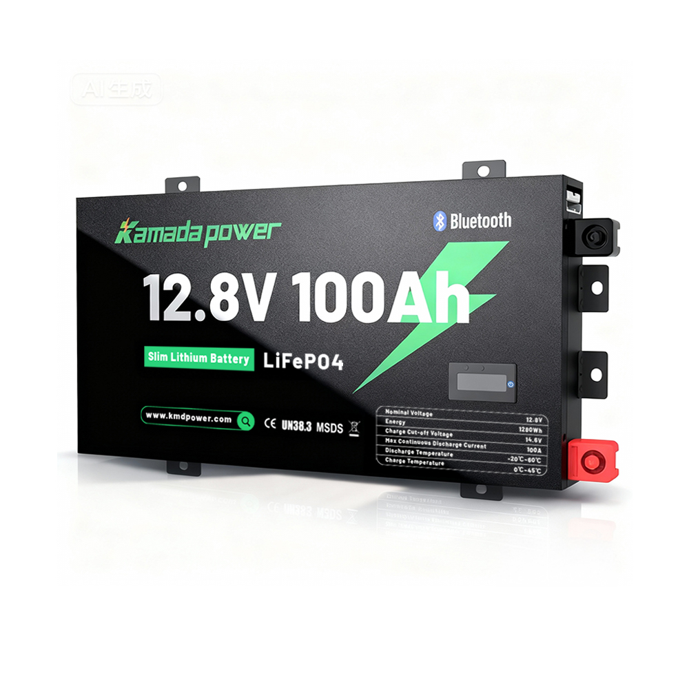
Kamada Power 12v 100ah slimline lithium battery
What Is a 12V Canopy Control Board?
A 12V canopy control board is the organized mounting and wiring platform for the auxiliary electrical system. It commonly includes:
| Function | Typical Components | Design Objective |
|---|
| Storage | Slimline LiFePO4 battery | Fit, secure mounting, terminal access |
| Charging | DC-DC charger, MPPT or combined charger | Correct voltage, current and thermal operation |
| Main protection | DC-rated fuse or breaker, isolator | Protect conductors and provide safe isolation |
| Monitoring | Shunt, display or communication interface | Measure all intended battery current |
| Distribution | Positive and negative busbars, fuse box | Clear, protected branch circuits |
| User control | Switch panel, sockets, USB-C, outlets | Simple operation without confusing service wiring |
| Documentation | Wiring diagram, fuse schedule, labels | Repeatable installation and faster fault finding |
The board should show a logical power path. An attractive board with crossed cables, hidden fuses, poor terminal clearance, or loads bypassing the shunt is not a professional design.
Start With the Installation Envelope
Slimline lithium batteries are selected for narrow spaces behind drawers, seats, canopy walls, wheel arches, or service panels. A nominal dimension is not enough. Confirm:
- maximum length, width and depth;
- terminal and protective-cover height;
- cable-lug and bend clearance;
- mounting direction approved by the battery supplier;
- bracket and restraint points;
- access to the main fuse, isolator, shunt and BMS reset or communication port;
- removal path without dismantling unrelated equipment;
- exposure to water, dust, cargo impact and heat;
- payload and structural limits.
A battery that fits the empty cavity may still fail installation once cable lugs, fuse holders, covers, drawers, trim, and service tools are included.
Map the Electrical Paths Before Placing Components
Use the current paths to determine the layout:
Vehicle source → source-side protection → DC-DC charger
→ charger output protection where required → auxiliary battery

Solar panel → compatible solar controller or DC-DC solar input
→ auxiliary battery / approved DC bus

Battery positive → main protection → isolator → positive busbar
→ branch fuse → switch or controller → load

Battery negative → battery side of shunt → system side of shunt
→ negative busbar → chargers and loads
The exact order of the main fuse and isolator depends on the approved design and device requirements, but the battery-connected conductor should be protected as close to its source as practical. Keep high-current cables short and direct, and separate them from low-level monitoring and communication wiring where practical.
Position the Battery First
The battery is normally the largest and heaviest component. Confirm more than amp-hours:
| Battery Item | Why It Matters |
|---|
| Continuous and peak BMS current | Must support combined loads and realistic surges |
| Recommended and maximum charge current | Limits DC-DC and solar charger selection |
| Charge-voltage range | Must match actual charger settings |
| Terminal type and orientation | Controls fuse placement and cable routing |
| Temperature limits | Affects cold charging and hot-canopy operation |
| Mounting restrictions | Prevents unsupported installation directions |
| IP rating | Applies to the tested enclosure, not the entire board |
| Series/parallel limits | Must be stated rather than assumed |
Do not place chargers, inverters, or hot air outlets directly against the battery unless the equipment suppliers have approved the thermal arrangement.
Main Fuse or Circuit Breaker
The main protection device primarily protects the positive conductor during a short circuit. It should not be selected from battery capacity alone.
Review:
- cable ampacity after temperature and bundling derating;
- normal and peak load current;
- battery fault-current capability;
- BMS limits and behaviour;
- cable length and routing exposure;
- downstream branch protection;
- equipment-manufacturer requirements.
A breaker is not automatically interchangeable with a fuse. Use a device explicitly rated for the system’s DC voltage and fault duty. Confirm DC interrupting capacity, terminal rating, environmental suitability, and whether the device is approved for repeated switching. A device that carries the normal current but cannot safely interrupt the possible fault current is not adequate protection.
The protection device should remain visible and replaceable. Hiding it behind fixed drawers or equipment encourages unsafe bypassing during service.
Battery Isolation Point
An isolator supports maintenance, storage, transport, and fault investigation. It should be:
- rated for the DC voltage and expected current;
- positioned in the intended main positive path;
- accessible without creating an unnecessarily long cable route;
- protected against accidental operation where needed;
- labelled consistently with the wiring diagram.
Isolation does not replace overcurrent protection, and a switch should not be opened under a load that exceeds its switching rating.
DC-DC Charger and Solar Input
A lithium setting alone does not prove compatibility. Confirm actual charge voltage, charge current, low-temperature behaviour, alternator compatibility, input-voltage range, ignition logic, solar limits, and whether alternator and solar inputs can operate together.
Mount the charger where:
- the cable route is practical;
- manufacturer-required cooling clearances are maintained;
- stored equipment cannot block vents or heatsinks;
- status indicators and terminals can be inspected;
- replacement does not require removing the battery or fuse box.
Select charger current from the battery’s allowed charge current, alternator spare capacity, driving time, simultaneous loads, cable route, and thermal derating. The largest charger is not automatically the fastest reliable solution.
Shunt and Negative-Side Layout
A shunt measures current only when that current passes through it. The normal arrangement is:
Battery negative → battery side of shunt
→ system side of shunt → negative busbar
→ all measured chargers and loads
Do not connect a charger, inverter, fridge, or accessory directly to battery negative if it is intended to be included in the monitor calculation. Label both shunt sides clearly.
The relationship between battery negative, the negative busbar, and vehicle chassis must be defined in the wiring diagram. A chassis bond may be required by the equipment or vehicle design, but uncontrolled mixtures of chassis returns and direct battery-negative returns can create inaccurate monitoring and difficult fault finding. Use the approved grounding method consistently across the fleet.
Busbars, Fuse Box, and Switch Panel
Busbars prevent excessive stacking of cable lugs on battery terminals and create clear connection points. Select them for the expected current and protect live positive surfaces against accidental contact.
The fuse box should:
- remain accessible with the canopy loaded;
- have a durable circuit map;
- use fuse ratings matched to each branch conductor and load;
- separate high-current circuits such as inverters or compressors where necessary;
- leave controlled spare capacity for approved future accessories.
The switch panel controls loads; it does not necessarily carry the full load current. High-current equipment may require a relay, contactor, or dedicated controller. Match switch, relay, connector, cable, and fuse ratings as one circuit.
Recommended Board Zones
A practical board usually separates:
- Battery and main protection zone — battery terminals, main fuse, isolator.
- High-current charging zone — DC-DC charger and major cable paths.
- Monitoring and negative zone — shunt and negative busbar.
- Distribution zone — positive busbar, branch fuse box, relays.
- User-control zone — switches, displays, sockets and labels.
- Communication zone — CAN, RS485, Bluetooth antenna clearance or monitor cables where used.
The zones do not have to be physically far apart. They need to be visually and electrically clear, with controlled crossings and serviceable cable bends.
Practical Layout Checklist
Before drilling the board, confirm:
- battery dimensions using the real sample;
- cable-lug orientation and bend radius;
- main-fuse access and replacement path;
- DC ratings and interrupt capacity of protection devices;
- charger and inverter cooling clearance;
- shunt battery side and system side;
- defined chassis-bond or negative-return method;
- no unprotected positive cable passing through sharp metal;
- grommets, abrasion protection and strain relief;
- torque values for battery, busbar and fuse connections;
- label visibility after drawers and cargo are installed;
- room to remove each service component;
- final wiring diagram and fuse schedule matching the as-built board.
Sample Validation for OEM and Fleet Projects
A sample should be tested as a complete board, not only as a battery.
Mechanical Review
Check fit, bracket stiffness, terminal clearance, cable bends, fuse access, drawer movement, cargo impact risk, service removal, and label visibility.
Electrical Review
Test the actual DC-DC charger, solar input, common loads, inverter if fitted, voltage drop, simultaneous charging and load operation, low-SOC wake-up, and BMS recovery after protection events.
Thermal Review
Operate the charger and high-current loads in a representative closed-canopy condition. Record component temperatures and any charger or inverter derating. A short bench test in open air does not validate a hot vehicle enclosure.
Production Review
Freeze the approved battery model, BMS settings, terminal orientation, board drawing, cable specification, fuse schedule, labels, torque requirements, firmware where relevant, and inspection photographs. Any later change should follow documented approval.
Information Required Before Quotation
Send the supplier or installer:
- canopy and board drawings;
- maximum battery space and removal path;
- battery voltage and target daily energy;
- continuous and peak loads;
- inverter rated and surge power;
- DC-DC charger and solar-controller models;
- solar array voltage and current limits;
- cable lengths and expected route;
- operating-temperature and exposure conditions;
- grounding method if already defined;
- fuse-box and switch-panel plan;
- monitoring and communication requirements;
- private-label, documentation and quantity requirements;
- sample pass/fail criteria.
This information prevents a technically capable battery from failing because of terminal position, charger mismatch, inaccessible protection, or an unsuitable board layout.
When a Slimline Layout Is Not Suitable
Reconsider the design when:
- the requested inverter exceeds the battery or BMS capability;
- the main positive conductor cannot be protected properly;
- the battery cannot be restrained or removed safely;
- the cable route becomes long, exposed, or difficult to protect;
- charger and inverter heat cannot be managed;
- the compartment is exposed to pressure washing or cargo impact without suitable protection;
- one universal board is expected to fit different vehicles without validating space, alternator behaviour, grounding, and service access.
Slimline packaging solves a depth problem. It does not remove electrical, mechanical, thermal, or compliance constraints.
Conclusion
A reliable 12V canopy control board begins with the complete current path, not the visible component arrangement. Position the battery first, protect source conductors correctly, use DC-rated protection with adequate interrupting capability, route all measured current through the shunt, define the negative and chassis strategy, and keep every service item accessible.
For OEM and fleet projects, lock the approved board as a controlled configuration with a wiring diagram, fuse schedule, labels, torque requirements, and commissioning record.Contact us to customize slimline lithium battery.
FAQ
Where should the shunt be installed?
Install it in the main negative path. Battery negative connects to the battery side; the negative busbar and all measured chargers and loads connect through the system side.
How close should the main fuse be to the battery?
The battery-connected positive conductor should generally be protected as close to the source as practical, subject to the approved design and applicable installation requirements. Select the device from cable protection, current, DC voltage, and fault-interruption needs—not battery Ah alone.
Can a circuit breaker replace the main fuse?
Only when it is explicitly suitable for the DC system, has adequate interrupting capacity, matches the conductor and load, and is installed according to its instructions. A similar current rating does not make two devices equivalent.
Should the DC-DC charger be mounted beside the battery?
Nearness can reduce cable length, but cooling clearance, water protection, terminal access, status visibility, and replacement space are equally important.
Can an inverter connect directly to the battery?
The inverter requires a dedicated, protected high-current circuit matched to the battery, BMS, cable, connector, shunt arrangement, and inverter surge demand. Do not add it as an unreviewed accessory.
Can one board design be used across several vehicles?
A common platform is possible, but each vehicle still needs validation for mounting, cable route, alternator behaviour, grounding, ventilation, payload, and service access.