An OEM builds a solar CCTV box around an all-in-one PoE switch that charges the battery and powers cameras. The switch ships with a LiFePO4 preset; the OEM wants to install a 12V-class sodium-ion pack. Nominal voltage does not make the preset compatible. The decision depends on the exact finished battery, the switch’s editable settings, and whether the complete system can charge and restart without interrupting surveillance. This is a model-specific qualification.
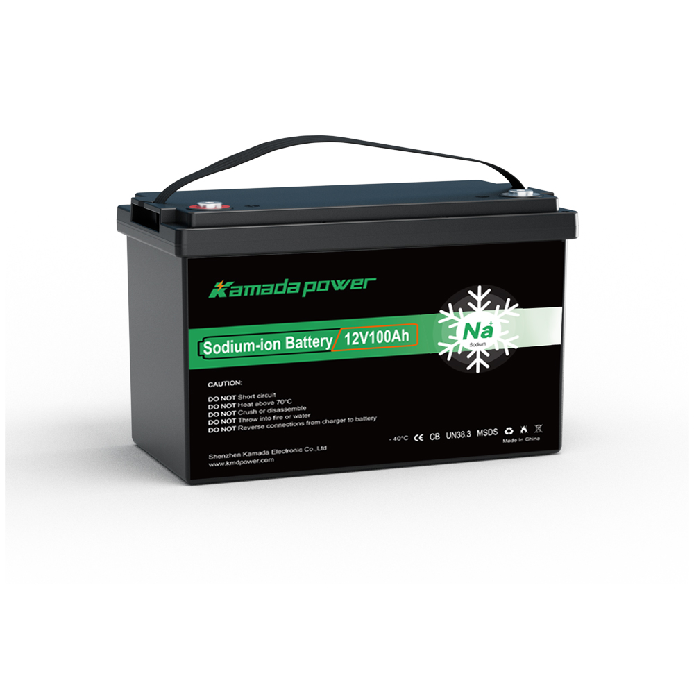
Kamada Power 12v 100ah Sodium ion Battery
What Does the Solar PoE Switch’s LiFePO4 Default Actually Specify?
Linovision’s POE-SW804G-SOLAR combines a four-port PoE switch with an MPPT solar charge controller. Its quick guide (V2.1, September 2, 2026) says that a battery other than 12V LiFePO4 must be configured using RS485 and PC software before connecting the solar panel. Charging is limited to 10A. The manufacturer’s manual gives the following LiFePO4 reference settings, not sodium-ion recommendations.
| POE-SW804G-SOLAR setting | LiFePO4 reference | Check against the exact sodium-ion pack |
|---|
| Charge / boost voltage | 14.4V | Approved charge target and regulation tolerance |
| Float voltage | 14.2V | Whether holding this voltage is permitted |
| Charging-current limit | 10A | Battery’s temperature-dependent charge-current limit |
| Charge termination current | 0.5A | Approved end-of-charge rule and sensing location |
| Controller overvoltage threshold | 15.0V | Protection coordination, not a charging target |
| Low-temperature charge protection | 0°C | Pack’s permitted charging temperature and current |
Changing boost alone while leaving incompatible float, termination, temperature or protection settings is not sufficient.
What Must Match the Finished 12V Sodium-Ion Battery?
Start with the finished battery pack, not a generic sodium-ion cell or a 12V label. The Kamada Power 12V 100Ah Sodium ion Battery datasheet supplied for this review specifies 1,200Wh nominal energy, a 15.6V maximum charge voltage, and a standard constant-current/constant-voltage procedure: charge at up to 0.2C (20A) to 15.6V, then hold 15.6V until current falls to 0.02C (2A). That standard procedure is stated for 0–45°C. It does not establish permitted float or BMS recovery behavior.
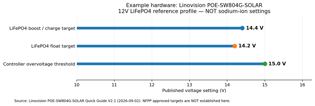
Compare the actual figures:
- 14.4V boost versus 15.6V specified CC/CV target: the default may charge the pack incompletely. This does not prove damage or full capacity.
- 15.0V controller overvoltage versus 15.6V target: leaving this protection setting unchanged could prevent the controller from reaching the pack’s documented standard charge voltage. Confirm coordinated, safe adjustment of both regulation and protection limits, including tolerances.
- 0.5A termination versus 2A datasheet endpoint: these are different termination rules. The difference requires manufacturer approval and battery-branch current testing.
- 10A controller limit versus the 20A standard-current example: A lower current is not necessarily prohibited. Confirm the acceptable current range and whether the solar window still meets required recharge energy.
For low-temperature charging, the supplied pack sheet lists 10A from -20 to -10°C and 20A from -10 to 0°C; above 0°C it lists a 50A maximum continuous charging current, subject to the exact revision and temperature controls. Do not override switch protection. Verify approved high-temperature derating too: the sheet’s overall charge-temperature range extends to 70°C, while its standard CC/CV procedure is specified only to 45°C.
The Kamada Power 12v 100ah sodium ion battery uses a 12.8V model designation and different dimensions from the supplied 12V datasheet. Do not combine those specifications into one approved SKU without revision confirmation. Kamada Power existing MPPT/PWM settings guide provides general context; this article concerns whether the specific PoE switch can implement an approved profile.
Does a Custom Battery Profile Make the Switch Compatible?
It makes compatibility possible. Linovision documents an RS485-to-USB connection and a PC configuration tool. Ask three questions for every relevant field: Can it be edited? Does its actual firmware allow the required range? Does it retain and execute the setting through charging and restarts? An input field does not prove sufficient range.
Check charge voltage, float behavior, termination current, overvoltage protection, low- and high-temperature rules, and charge-current limiting as a coordinated set. In particular, the supplied 15.6V pack charge target cannot be considered compatible while the controller’s 15.0V reference overvoltage setting remains in force. The proper protection threshold and margin must be approved by both manufacturers; do not invent a higher setpoint.
Disable any lead-acid equalization or unapproved temperature-based voltage compensation. That is different from temperature-based charging permission or current limits. Use the BMS for protection, not as a routine overcharge termination method. If a required field is fixed, undocumented or outside the allowable range, reject that controller configuration and consider a separate approved charger or another power architecture.
What Happens During a Short or Cold Solar Charging Window?
This switch is not charging an isolated battery on a bench. Its solar input may support cameras, a router and charging through a shared DC path. Controller output current is not automatically net battery charge current. Measure the battery branch separately, and convert loads to a common voltage or power basis before subtracting current values.
For example only, if 10A reaches a common 12V-class DC bus and its live loads draw 3A at that same bus, about 7A might enter the battery, ignoring losses and other paths. Returning 70Ah ÷ 7A = 10 hours is only ideal constant-current arithmetic; PV variation, voltage taper and nighttime consumption make actual recovery longer or uncertain. Do not subtract a PoE port’s output current directly from battery current: the voltages differ. The Linovision 12V system also has a 60W total PoE budget and a 5A maximum load output, so test peak camera, IR and auxiliary demand against the correct ratings.
Temperature creates another mismatch. Linovision’s LiFePO4 reference blocks charging below 0°C and discharging below -20°C, with 55°C charge and 60°C discharge high-temperature thresholds. The supplied KMDPOWER sheet permits conditional charging below freezing and lists discharge down to -40°C, but it does not document identical current capability at all temperatures. The default could block a battery operation that the pack permits; changing the cutoffs is justified only after both manufacturers approve the entire operating range, including the controller’s own limits.
A cold morning may therefore leave a battery unrecharged even when daylight returns. Midday may expose another recharge shortfall. Neither outcome is solved by copying another chemistry’s preset.
How Should an OEM Qualify the Solar PoE Switch and a Sodium-Ion Pack?
Test the installed power system: exact pack and BMS revisions, switch firmware, PV input, wiring, fuses, and live CCTV loads. Controller-only tests cannot certify unattended operation.
1. Freeze both specifications. Obtain the saved controller profile and an approved pack charge instruction for the exact shipment. Compare voltage, tolerances, termination, float, current-versus-temperature limits, low-voltage thresholds and BMS recovery. Resolve the 12V versus 12.8V listing difference rather than combining revisions.
2. Confirm adjustment and persistence. Follow Linovision’s connection order: load → battery → solar panel, configuring a non-default battery after battery connection and before PV connection. Read back all relevant settings and verify them again after a permitted power cycle. Do not test by forcing an overvoltage trip.
3. Measure at the battery terminals. During approved charging, log controller output, battery-terminal voltage, net battery-branch current, battery temperature and BMS charge permission. Record voltage regulation, current taper and termination with and without the continuous CCTV load. A “charging” indicator does not prove battery charging current.
4. Add the real camera load. Include cameras, IR illumination, communications gear and applicable auxiliary loads. Verify the 60W total 12V PoE budget, 5A load-output limit, and any separate connector limits. Confirm camera uptime while the controller changes charging states, including cloud interruptions and recovery.
5. Test permitted temperature boundaries. Compare the controller’s 0°C/-20°C default protections with the battery maker’s approved conditional charging and discharge ranges. Use controlled temperatures and check sensor locations. Never force current into a battery outside approved limits.
6. Review the recovery day. The Linovision installation manual says a 12V battery must be above 9V to initiate controller operation. The KMDPOWER sheet lists an 8V discharge cutoff—not a guaranteed BMS output or recovery voltage. After a deep discharge or BMS isolation, verify that the controller can actually restart and resume camera power; a PV panel appearing at sunrise is not proof of autonomous recovery. Also confirm that low-voltage load-disconnect and reconnect settings preserve enough margin for cameras to remain online.
Measure battery charge energy (Wh) = ∫ battery-terminal voltage × measured net battery charging current dt over the approved charge interval, and separately track load energy and PV production. Record fault cause and recovery, not just a successful midday charging event.
When Should the OEM Keep the Switch, Change It, or Reject the Battery Pairing?
The result must support a procurement decision, not just a settings list.
| Verified finding | Procurement or design decision |
|---|
| All voltage, termination, temperature and protection settings can meet the approved pack requirements; system tests pass | Qualify this configured switch and exact battery revision |
| The 15.6V pack charge requirement cannot be coordinated with the controller’s adjustable charging and overvoltage limits | Change the charging architecture or switch; do not rely on BMS trips |
| Float or low-temperature behavior cannot match the battery’s approved profile | Reject the default profile and use an approved alternative |
| Charging is safe, but 10A maximum and available solar hours cannot replenish daily consumption | Reassess PV, charging capacity and daily energy balance |
| PoE load exceeds rating, or camera service drops during charging transitions | Correct the load/power path before buying more battery capacity |
| A BMS shutdown prevents the controller from reaching its >9V startup condition | Hold approval until an automatic recovery path is verified |
Manufacturer-approved parallel packs add reserve, not a higher nominal voltage or more than the switch’s 10A charging capacity. A larger bank may extend backup duration while increasing the time needed to recharge. Document firmware, limits, branch currents, recovery, temperature behavior and camera continuity.
FAQs
Can a charger set to 14.4V automatically charge a 12V-class sodium-ion battery?
No. The exact finished pack determines the approved profile. This supplied KMDPOWER datasheet specifies a 15.6V standard CC/CV target; a 14.4V default might charge partially, but cannot be assumed to achieve the specified charge endpoint or usable capacity.
If the switch offers a lithium setting, is that enough?
No. A lithium label does not identify pack voltage limits or BMS behavior. Check the switch’s editable charging, termination, protection and temperature settings against the exact pack revision, then test the system.
Can the BMS protect the pack from the wrong charge profile?
A BMS is protective backup, not normal charge regulation. Repeated protection trips can disrupt charging and CCTV operation. Use an approved controller profile and verify BMS recovery separately.
Should a solar PoE controller keep float charging a sodium-ion battery?
Only if the battery manufacturer approves the voltage and hold behavior for that pack. The switch’s 14.2V LiFePO4 float is neither automatically safe nor necessary for the sodium-ion configuration.
Does a 10A solar charger fully recharge a 100Ah battery in ten hours?
Not necessarily. 100Ah ÷ 10A = 10 hours is an idealized current calculation, not a solar-site forecast. Live camera loads, PV variability, current taper, temperature limits and charge losses may lengthen recovery substantially.
Conclusion
An all-in-one solar PoE switch built around LiFePO4 settings may be configurable for a 12V sodium-ion battery pack, but its defaults are not qualified merely because both systems say 12V. For the supplied Kamada Power 12V 100Ah Sodium ion Battery specification, the 15.6V charge target, 2A standard termination endpoint, conditional cold charging and 8V discharge cutoff expose concrete checks against this Linovision switch’s reference settings—and its >9V startup requirement. Verify the real firmware adjustment range, battery-branch charging, peak PoE load and unattended restart before approving the pairing. For broader guidance see Kamada Power MPPT/PWM settings article. Contact Kamada Power with the switch firmware, settings export, battery revision, site temperatures and expected volume to request a model-specific compatibility review.