A 12V camera and a 12V-class battery may look compatible, yet the camera can reboot during discharge or face excessive charging voltage. Before replacing a conventional battery with a 12V 100Ah sodium-ion battery, an OEM must check whether every voltage the camera sees stays within its approved input range.
A direct connection is eligible for consideration only when the verified voltage at the camera terminals stays within its permitted range during charging, loaded discharge, startup and relevant transients and the power source meets the camera manufacturer’s safety and installation requirements. A “12V” label proves neither. Otherwise, use a qualified supply or change the architecture.
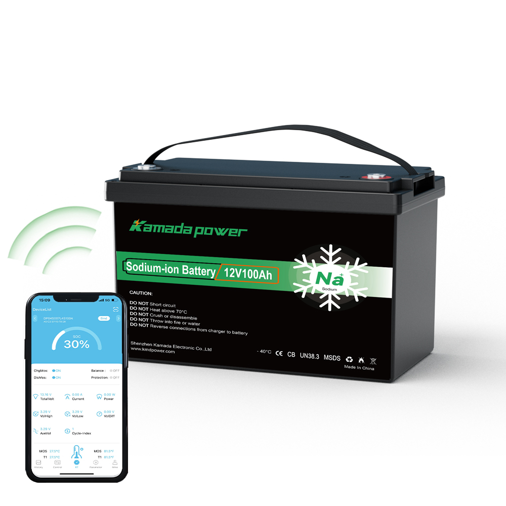
Kamada Power 12v 100Ah Sodium-ion Battery
What Voltage Does a 12V CCTV Camera Really Allow?
The label describes a nominal supply category, not a universal tolerance. A Bosch DINION IP starlight 6000 HD variant specifies 12V DC ±10%, or 10.8–13.2V, on its auxiliary input. The AXIS P1388 box camera specifies 10–28V DC. These are model-specific limits.
A camera rated for 10.8–13.2V is not protected from a higher charging voltage merely because its connector says 12V. Nor does a battery’s discharge cutoff define the camera’s minimum operating voltage.
Reference specifications and the overlap problem
| Published equipment specification | DC voltage range | What it establishes |
|---|
| Bosch DINION IP starlight 6000 HD, applicable auxiliary-input variant | 10.8–13.2V | A narrow camera input window |
| AXIS P1388 box camera | 10–28V | A wider camera input window |
| KMDPOWER 12V 100Ah sodium-ion battery datasheet, supplied configuration | 15.6V charge maximum; 8V discharge cutoff | Specified limits, not a measured continuous output curve |
Source notes: Bosch camera datasheet; Bosch installation manual; AXIS P1388 specifications; AXIS user manual. Battery figures are from the supplied Kamada Power datasheet; confirm its revision.
These figures already expose a mismatch. On an unregulated shared bus that reaches the battery’s 15.6V charging limit, the Bosch example would exceed its 13.2V maximum by 2.4V. AXIS accepts 15.6V within its published DC range, but its 10V minimum is above the battery’s 8V discharge cutoff. AXIS needs a verified early cutoff or power conversion; voltage labels alone cannot approve either connection.
What Voltage Does a 12V-Class Sodium-Ion Battery Actually Deliver?
A 12V-class battery is not a regulated 12.0V supply. The Kamada Power datasheet for the supplied 12V 100Ah configuration specifies 12V nominal, 100Ah, 1,200Wh nominal energy, 15.6V maximum charging voltage and 8V discharge cutoff. These endpoints are not a continuous output curve. Loaded-voltage behavior, BMS recovery thresholds and transients remain unverified.
The Kamada Power 12V 100Ah Sodium ion Battery uses a 12.8V model designation. Do not treat the catalogue and supplied datasheet as the same approved revision without confirmation.
For camera compatibility, the engineer needs four separate answers:
- At rest: What terminal voltage occurs across the intended state-of-charge range?
- Under load: How far does voltage dip at the actual camera current and temperature?
- During charging: What voltages can the approved charger place on the battery and shared DC bus, including transitions?
- During protection: When does the BMS interrupt discharge or charging, and how does the system restart?
The 8V figure is a discharge cutoff, not a promise that a camera can operate down to 8V. The BMS protects the battery; it does not guarantee uninterrupted CCTV power. Charging compatibility must be checked separately.
A voltage-window view for a proposed direct connection
                    LOW VOLTAGE       NOMINAL       HIGH VOLTAGE
Battery bus    [verified loaded minimum ------ verified charging maximum]
Camera input      [manufacturer minimum ------ manufacturer maximum]

DIRECT CONNECTION may be tested only if the entire voltage window seen at
camera terminals fits the camera window AND source safety rules are met.
This is not a measured curve. Test with the approved charger: the camera may see charging-bus voltage.
Why Can the Camera Voltage Differ from the Battery Terminal Voltage?
In a pole-mounted CCTV cabinet, the battery, fuse, connector, distribution board, camera and sometimes an LTE router share a DC path. Cable and connector resistance causes voltage drop, especially near the camera’s minimum input or when accessories start.
Voltage drop = current × total circuit resistance. At a hypothetical 1.5A through 0.20Ω of total loop resistance, drop is 0.30V. If the battery terminals read 10.9V, the camera would receive about 10.6V in this simplified steady-state example—below the Bosch example’s 10.8V minimum. This is illustrative, not a KMDPOWER test or wiring recommendation.
The Electrical Installation Guide addresses voltage at the load terminals, not only at the source. Check cable length, conductor size, connectors and actual current.
Measure at the camera power connector with the installation operating. Repeat near the planned minimum service voltage, at startup and with applicable accessories running. IR lighting, motors, heaters and outdoor housings may change peak demand; the camera body’s published consumption is not necessarily the entire site’s load. Brief dips may require fast recording rather than a handheld meter.
When Is a Direct Battery Connection the Wrong Choice?
A successful startup cannot rule out three problems.
First, the upper limit. On an unregulated bus approaching 15.6V during approved charging, the Bosch example’s 13.2V limit would be exceeded. Cable drop is not a reliable overvoltage safeguard. A camera powered through an independent regulator must instead be assessed at that regulator’s output.
Second, the lower limit. The AXIS example requires at least 10V DC, while the supplied pack datasheet lists an 8V discharge cutoff. A project may use a higher, validated shutdown threshold, but the 8V endpoint alone cannot justify direct connection. Extra Ah—or manufacturer-approved packs in parallel—extends potential runtime without fixing a voltage mismatch. Parallel connection does not increase nominal bank voltage.
Third, uncontrolled transitions or noncompliant supply conditions. Charger startup, BMS switching and neighboring DC loads can disturb the bus. Beyond voltage, the Bosch installation manual requires an approved 12V auxiliary supply with output isolated from earth; AXIS specifies a SELV-compliant limited power source (LPS) for its DC connector, with a rated output limited to 100W or 5A. A battery’s 100A discharge rating is not evidence that its direct output meets LPS requirements. Check the exact manuals, protection and wiring topology before approving any connection.
Should the OEM Add a DC-DC Regulator?
A properly selected buck-boost regulator can hold a controlled camera voltage while the battery voltage moves above and below the desired output. For a narrow-range 12V camera, this may be necessary even when the battery also says 12V.
Verify the regulator’s input range across the chosen service window, output tolerance, startup and restart behavior, peak current, ripple, temperature limits and behavior when the BMS opens. An early regulator shutdown can leave energy in the pack; a shutdown set too low can violate approved system limits. The regulator or power-supply assembly must also satisfy the camera’s isolation, SELV/LPS or other applicable source requirements. A fuse alone does not establish that compliance.
Design for actual loads, including camera startup and enabled accessories. For PoE cameras, check the DC input to the PoE injector or switch, plus its input and output power budgets; do not apply the camera’s auxiliary-DC range to the PoE feed. Qualify direct DC, regulated DC and DC-powered PoE separately.
Engineering decision table
| Finding after model-specific review | Recommended outcome |
|---|
| Camera-terminal voltage meets the full input range and power-source requirements are satisfied | Direct DC connection may be qualified by full-system testing |
| The pack’s charging limit exceeds the camera’s upper input limit | Use an appropriate regulated supply or change the architecture |
| Camera minimum input exceeds the planned low-voltage service limit | Set and verify an earlier system cutoff or use a suitable regulator |
| Regulator input, restart behavior, isolation or power limitation is inadequate | Change the regulator or power architecture; extra Ah is not the remedy |
| Battery revision, BMS behavior, charging limits or camera source requirements cannot be confirmed | Hold or reject the design until those conditions are resolved |
An unattended site needs documented testing, not one successful startup.
How Should a CCTV OEM Test Battery-to-Camera Voltage Compatibility?
Use the exact camera, battery revision, charger, harness and any DC-DC or PoE equipment intended for production. Review approved limits and supply safety requirements before energizing the assembly. Then test:
1. What happens during normal camera startup? Record battery-terminal and camera-input voltage, current and peak load with required accessories enabled. Confirm the camera input stays within specification.
2. What happens late in discharge? Repeat under a controlled discharge near the planned system shutdown threshold, which must respect the camera, regulator and battery limits. Do not use 8V, the pack’s stated discharge cutoff, as an automatic camera operating target or bypass BMS protection to test deeper discharge.
3. What happens when solar charging resumes? Set the charger for the exact approved pack revision and verify its specified 15.6V maximum is not exceeded at the battery. Record camera-facing voltage during charger start and regulation; a shared bus may expose the camera to the higher charging voltage.
4. What changes with temperature? Repeat relevant points at project temperatures within the approved limits of all devices. The supplied pack datasheet lists temperature-dependent charge-current limits; verify the applicable charge program and any high-temperature derating before testing.
5. Which device fails first? If video drops, correlate camera-input voltage, regulator or PoE power status, charger output and BMS state. Record whether the system recovers automatically after a protective shutdown; an offline camera does not by itself prove BMS failure.
Log revisions, settings, load states, minimum and maximum camera voltage, temperature, failures and recovery. These are proposed test requirements, not claims that KMDPOWER equipment has already passed them.
What Should an Integrator Request Before Replacing an Existing CCTV Battery?
An OEM can begin with camera model numbers and power-input manuals, charger details, simultaneous loads, site temperature and a basic wiring diagram. Include the selected architecture: direct DC, regulated DC or DC-powered PoE.
Request the approved finished-pack datasheet for the exact Kamada Power revision, plus BMS protection/recovery settings and loaded-voltage data. The supplied 15.6V charging maximum and 8V discharge cutoff are useful screening limits, but not a substitute for those measurements. Manufacturer-approved parallel expansion may increase runtime; it cannot fix voltage or supply-safety incompatibility.
For broader context, see 12V sodium-ion batteries for security systems and the 12V 100Ah Sodium ion Battery. This article addresses camera-terminal voltage and power-source compatibility, not general CCTV battery sizing.
FAQs
Does “12V camera” mean it can connect directly to any 12V sodium-ion battery?
No. Compare the manufacturer’s DC input window against the voltage actually reaching the camera during charge, discharge and transitions. Also check the specified power-source safety requirements.
Is a 12V-class sodium-ion battery voltage too low for a 12V CCTV camera?
Not necessarily. Camera ranges differ. The supplied KMDPOWER datasheet lists 8V discharge cutoff, but a camera or converter may require a higher shutdown threshold. Nominal voltage is not enough to decide.
Does adding a second 12V 100Ah battery solve a camera voltage mismatch?
No. Manufacturer-approved parallel packs can increase stored energy and load sharing but do not change nominal system voltage. The mismatch still requires a different cutoff, regulator, power architecture or device.
Can a DC-DC converter make the system compatible?
Often, if its input window, output regulation, protection, thermal limits, restart behavior and applicable isolation or limited-power requirements are suitable. Test it with the camera and charger, not just a resistive load.
Conclusion
A 12V CCTV camera can run from a sodium-ion battery only when the actual camera-input voltage and power-source requirements are met throughout the intended operating states. For the supplied Kamada Power 12V 100Ah specification, 15.6V maximum charging voltage and 8V discharge cutoff make model-specific screening essential: the Bosch example has a narrower upper limit, while the AXIS example has a higher minimum operating voltage than the pack’s cutoff. Neither observation replaces system testing. For a project review, contact Kamada Power with camera input specifications, wiring architecture, charger settings, temperature range and expected purchase volume. Request a revision-specific compatibility assessment before sampling or production.