Miten asennan istuimen taakse asennettavan laitteen? Ohut litium-akku AU Dual Cab -ohjaamossa ilman Reworkia? (10 ansoja). Jos olet koskaan toimittanut "puhdasta istuimen takana olevaa ohutlinjaista litium-sarjaa" kaksoisohjaamoon, olet nähnyt sen: ensimmäisenä päivänä näyttää OEM:ltä ja amme pysyy vapaana seitsemäntenä päivänä saat puhelun, koska istuin ei lukkiudu, DC-DC on keittämässä tai invertteri piippaa alijännitettä, kun vedenkeitin tai kahvinkeitin käynnistyy, ja kaikki syyttävät akkua. Totuus on, että Useimmat viat ovat pakkauksen, jännitehäviön ja lataussuunnittelun - eivät Ah:n - aiheuttamia..
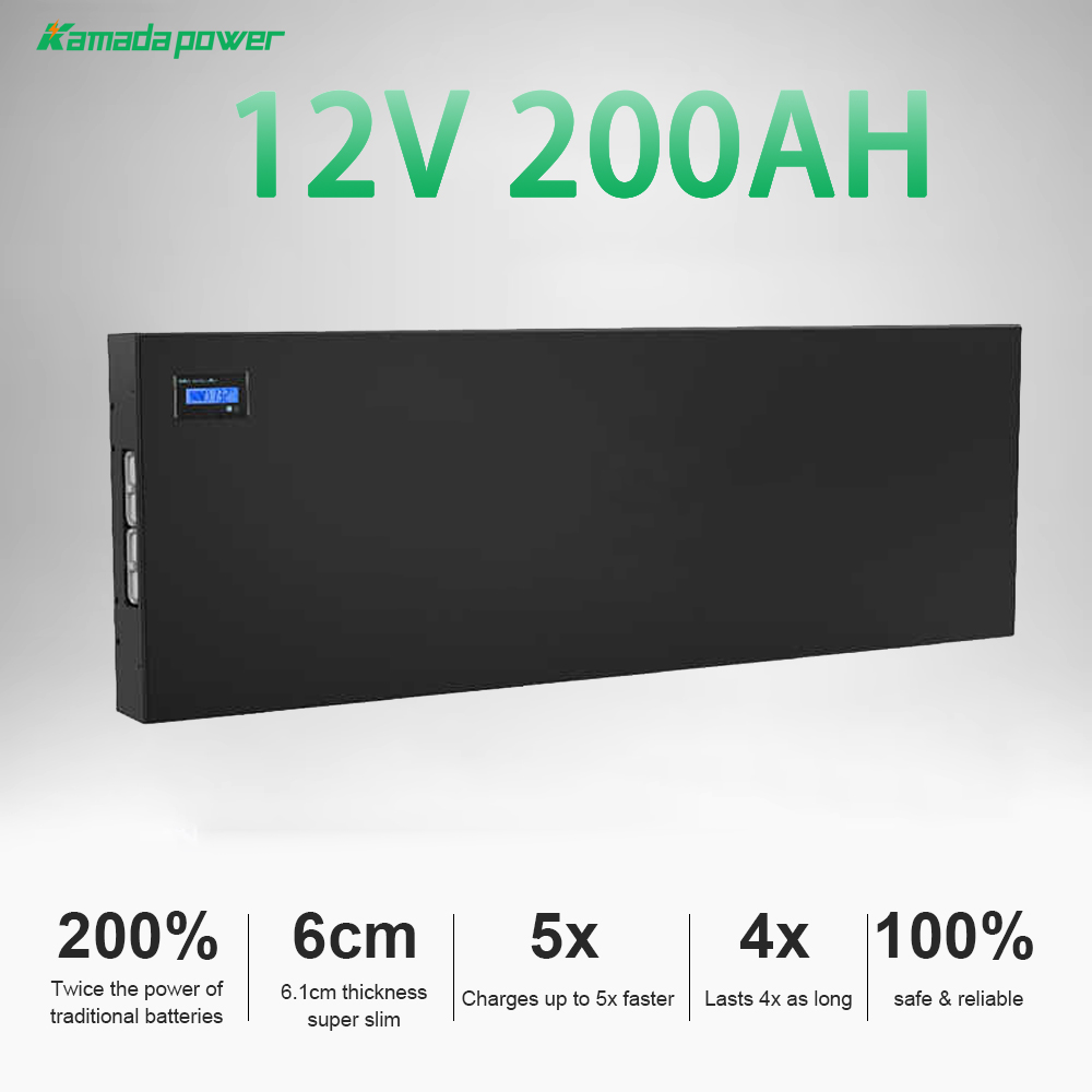
Kamada Power 12v 200Ah Slimline litiumakku
Miksi istuimen takana oleva Slimline Lithium on niin suosittu AU:n kaksoishyttiohjaamoissa
Mitä istuimen takana ratkaisee
Istuimen taakse asennettavat ohutlinjaiset asennukset ovat suosittuja, koska ne ratkaisevat hyvin todellisia rajoitteita:
- Tilatehokkuus: ohut LiFePO₄-akku sopii sinne, minne perinteinen "laatikko" ei mahdu.
- Varkaudenkestävyys ja estetiikka: Sisällä ohjaamoon on vaikeampi päästä käsiksi ja se näyttää siistiltä.
- Uimurin käytettävyys: kauppiaat ja laivastonhoitajat pitävät ammeen auki hyötykuormalle.
- Puhtaampi valjastaminen: vähemmän altistuminen säälle ja pölylle verrattuna ulkoisiin kiinnikkeisiin.
Mutta se aiheuttaa myös ennustettavaa teknistä päänvaivaa:
- Tiiviimpi ilmavirta: kaikki kulkee lämpimämmin verhoilun ja maton takana.
- Liikkuvat istuinmekanismit: kiskot, saranat, salpojen kohdat - asiat, jotka hankaavat tai puristavat kaapeleita ajan mittaan.
- Pidemmät kaapelit: invertteri ja jakelu päätyvät usein kauemmas akusta.
- Korkeammat turvallisuusodotukset: matkustamoon asennettava energiavarastojärjestelmä on asennettava niin kuin sillä olisi merkitystä - koska sillä on merkitystä.
Kokemuksemme mukaan teollisuus- ja autokanta-asiakkaiden kanssa työskennellessämme istumapaikan takainen lähestymistapa voittaa yleensä pakkaus- ja varkausriskin, mutta se pysyy "puhtaana" vain, jos sähkösuunnittelua käsitellään järjestelmänä, ei osien kokoelmana.
Kun istuimen takana istuminen on väärä valinta
Joissakin rakennuksissa istuimen takana on yksinkertaisesti väärä arkkitehtuuri, vaikka akku "sopisi":
- Suuret jatkuvat invertterikuormat (esim. raskaiden laitteiden päivittäinen käyttö, pitkäaikainen käyttö).
- Nolla-ilmavirtauksen ontelot jossa DC-DC-laturit ja invertterit termisesti laskevat.
- Ei turvallisia kiinnityspisteitä (kaikki, mikä on riippuvainen muoveista, on punainen lippu).
- Raskaat istuinpainealueet jossa istuimen selkänoja kuormittaa fyysisesti akkua tai johdotusta.
Näissä tapauksissa on usein parempi käyttää nopeaa vaihtoehtoa: a kuomun sivupaneeli, a suljettu kylpyamme laatikkotai Aluslaatikko ratkaisu - kullakin on omat kompromissinsa altistumisen, huollettavuuden ja kaapelin pituuden suhteen.
Istuimen taakse asennettavat järjestelmät vähentävät yleensä varkausriskiä ja säästävät lastitilaa, mutta ne voivat lisätä työaikaa ja käyttöönottovaatimuksia. Katos- tai koteloasennukset helpottavat usein ilmavirtausta ja huoltoon pääsyä, mutta ne voivat lisätä altistumista ja vaatia parempaa ympäristötiivistystä (pölyn ja veden pääsy). Hankinnan kannalta: valita vaihtoehto, joka minimoi omistuksen kokonaiskustannukset.-ei vain komponenttikustannuksia.
Sovituskolmio: Koko + istuimen liike + huoltopalvelujen saatavuus
Loukku #1: Mittaa vain paksuutta, ei koko kirjekuorta.
"Akun paksuus" on numero, jota kaikki lainaavat. Se on myös numero, joka aiheuttaa repeämiä.
Istuimen takana olevat ontelot eivät ole suorakulmioita. Istuimen selkänojan ääriviivat, verhoilun ulkonemat, maton pullistumat ja joskus yllättävät geometrian muutokset alhaalta ylöspäin. Ero mitattu rako ja käyttökelpoinen aukko on yleensä paikka, jossa asennus menee pieleen.
Ennaltaehkäisy: mitataan ontelo kolmella pystysuuntaisella vyöhykkeellä - matalalla, keskellä ja korkealla - ja otetaan huomioon koko istuimen liikekehä. Lisää sitten vapaat tilat päätelaitteille ja kaapeleiden ulostuloille. Jos istuinta ei voi sulkea sulavasti kädellä, se ei kestä vuoden mittaista todellista ajoa.
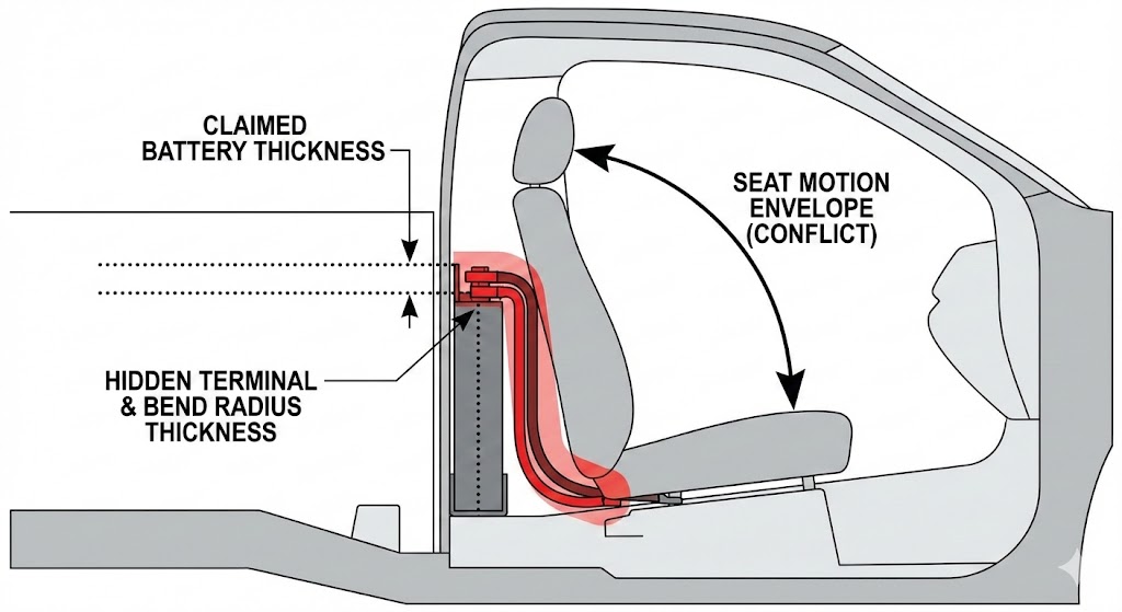
Kuten kuvasta käy ilmi, vain akun rungon paksuuden mittaaminen on ensisijainen syy jälkitöihin. On varattava riittävästi "kuoritilaa" päätelaitteiden ulkonemille, paksujen kaapeleiden pienimmälle taivutussäteelle ja istukan liikeradalle puristuksen jälkeen. Jos istuin vaatii voimaa napsahtaakseen paikalleen, kaapelit puristuvat.
Loukku #2: Liittimien ja kaapelin taivutussäteen unohtaminen
Ohut akku voi sopia täydellisesti... kunnes lisäät liittimet ja kaapeloinnin.
Päätelaitteet lisäävät "piilotettua paksuutta". Samoin sulakkeenpitimet, virtakiskot ja raskaiden johtimien taivutussäde. Jos tasavirtapolkusi sisältää 2/0-kaapelia (tai vastaavaa metristä poikkileikkausta), se ei halua tehdä jyrkkiä käännöksiä verhoilun takana. Se työntyy takaisin. Kirjaimellisesti.
Käytännön sääntö: suunnittele oma kaapelikaista ja vedonpoisto. Jos kaapeli on pakotettu tiukkaan mutkaan, vastus kasvaa, lämpö kasvaa ja kiinnityskorvakkeet löystyvät lopulta.
Trap #3: Ei palvelunkäyttösuunnitelmaa
Jos teknikko ei pääse käsiksi sulakkeisiin, DC-DC-resetointiin tai eristyskytkimeen irrottamatta istuinta, suunnitteluun on sisällytetty jälkitöitä.
Käytä kahden minuutin sääntö: Voitko eristää, tarkistaa sulakkeet ja nollata ne ilman istuimen irrottamista? Jos et, se ei ole "puhdas" asennus - se on piilotettu tuleva työlasku.
Asennus ja turvallisuus: #1: Matkustamon akkujen maineriski
Loukku #4: Asennus, joka ei ole törmäysturvallinen
Litiumparisto on tiheä. Matkustamossa sillä on merkitystä.
Huonosti asennetusta patterista tulee törmäyksessä ammusriski. "Törmäysturvallinen" tarkoittaa, että kiinnityspolku siirtää kuorman rakennepisteisiin käyttämällä asianmukaisia kiinnikkeitä, taustalevyjä ja kiinnikkeitä - ei verhoilupaneeleja. Se tarkoittaa myös sitä, että akku ei voi siirtyä, hankauttaa johdotuksia tai muuttaa ympäröiviä osia tärinän vaikutuksesta.
B2B-ostajille tämä on muutakin kuin turvallisuutta - se on vastuunhallintaa. Puhdas mekaaninen suunnittelu vähentää riitoja, vakuutuskysymyksiä ja mainehaittoja.
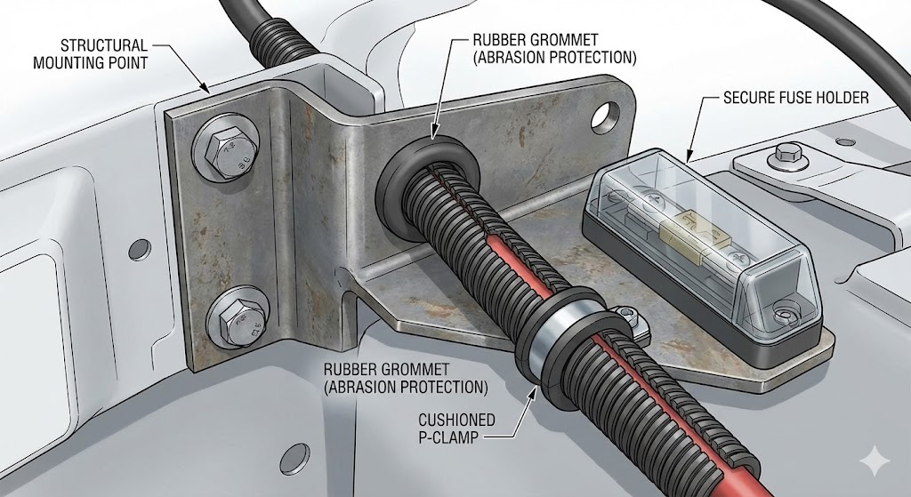
Kuten kuvassa näkyy, tämä asennus on suunniteltu kestämään Australian takamaaston ankarat olosuhteet ja mahdolliset iskut. Huomaa rakenteelliset metalliset kiinnityspisteet, kumiset kaapelinsuojaholkit kulumisen estämiseksi ja standardoidut kaapelikiinnikkeet. Nämä näennäisesti pienet yksityiskohdat ovat ratkaisevia sähköpalojen ehkäisemiseksi ja pitkäaikaisen luotettavuuden varmistamiseksi.
Loukku #5: Reunasuojien ja kulumisreittien huomiotta jättäminen.
Istuinkiskot, salpojen kohdat, saranoiden kaaret ja terävät metallilevyn reunat ovat kaapelin tappajia. Vikaantumistapa on ovela: järjestelmä toimii viikkoja, sitten "satunnaisesti" ilmenee ajoittainen oikosulku tai häiriösulake.
Käytä asianmukaista läpiviennit, jaettu putki, P-kiinnikkeetja vedonpoisto. Käsittele jokaista läpivientiä kulumiskohtana. Jos kaapeli voi liikkua, se liikkuu.
Asentajan todisteellinen pakkaus
Ammattitaitoiset asentajat vähentävät riitoja dokumentoimalla:
- Kiinnityspisteet ja kiinnikkeet (kuvat)
- Sulakkeiden sijoitus ja nimellisarvot (merkintä + kuva)
- Kaapelien suojaus läpivientikohdissa (kuva)
- Käyttöönottohuomautukset: jännitelukemat + havaittu latauskäyttäytyminen
Hankintaryhmät pitävät tästä, koska siitä tulee hyväksymiskriteereitä. Insinöörit rakastavat sitä, koska se muuttaa "minusta se on hyvä" muotoon "me mittasimme sen".
DC-DC-lataus: Missä istuimen takana olevat rakennelmat voittavat tai epäonnistuvat
Trap #6: "Litium-päivitys" ilman latausmallia.
Nykyaikaisissa ajoneuvoissa käytetään usein älykkäitä vaihtovirtageneraattoreita (vaihtuva jännite, ECU-ohjattu). Yksinkertainen eristysstrategia, joka toimi AGM-akkujen kanssa, voi olla tehottomampi tai käyttäytyä epäjohdonmukaisesti LiFePO₄-akkujen kanssa.
Tämän vuoksi DC-DC-laturi on usein oikea reitti vakaaseen litiumin lataukseen: se hallitsee latausprofiilia (irtolataus/absorptio/flotaatio), rajoittaa virtaa sopivasti ja pystyy käsittelemään generaattorin käyttäytymistä paremmin kuin "tyhmä" yhteys.
Todellinen käyttötapaus #1: laivaston kaksoisohjaamot lyhyet päivittäiset reitit. Ilman DC-DC:tä akku ei koskaan saavuta täyttä varaustilaa, ja takuukorvausvaatimukset alkavat näkyä "akun kapasiteetin menetyksenä", vaikka todellinen ongelma on krooninen vajaalataus.
Trap #7: DC-DC-sijoitus, joka ylikuumenee ja purkautuu.
Istuimen takana olevat ontelot ovat lämpimiä. DC-DC-laturit tuottavat lämpöä. Kun nämä kaksi yhdistetään, saadaan lämpöhäviö.
Lämmönlähteitä ovat muun muassa suljetut ontelot, matto/verhoilueriste ja heikko ilmavirta. Monet laturit suojaavat itseään vähentämällä tehoa, joten asiakas sanoo, että "se lataa joskus".
Ennaltaehkäisy: rakenna ilmavirtausta suunnitteluun. Jätä laturin ympärille todellinen ilmarako, asenna se pinnalle, joka voi johtaa lämpöä, ja vältä kuumien komponenttien kasaamista yhteen.
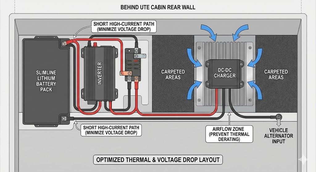
Kuten kaaviosta näkyy, optimaalinen asettelu on tasapainoilua: invertteri sijoitetaan lähelle akkua, jotta se täyttää suuren virran vaatimukset (jännitehäviön minimoiminen), samalla kun DC-DC-laturi "eristetään" ilmavirran ulottuvilla olevalle alueelle ja asennetaan jäähdytyselementin alustalle, jotta estetään ylikuumenemisesta johtuva lataustehokkuuden heikkeneminen.
Trap #8: DC-DC:n asettaminen väärään sähköiseen paikkaan.
Laturin sijoittaminen lähelle kampiakkua (lyhyempi generaattorin syöttö) ja lähelle kotiakkua (lyhyempi laturin ja akun välinen matka) on kompromissi. Pakkaus pakottaa usein tekemään päätöksiä.
Tässä on avain: jännitehäviö näkyy siellä, missä sitä vähiten haluat - laturin ja akun välissä. Laturi saattaa "luulla" antavansa oikean jännitteen, mutta jos akun napoihin tulee vähemmän jännitettä kaapelin häviämisen vuoksi, lataus on hidasta ja imeytyminen epätäydellistä.
Käyttöönottovaihe: toimenpide klo akun napoja latauksen aikana, ei vain laturilla.
Jännitehäviö ja kaapelisäännöt
Trap #9: Alimitoitettu kaapeli 12 V:n suurvirtaisilla poluilla.
12 V:n järjestelmät ovat armottomia, koska virta kasvaa nopeasti suureksi. Ja tappiot skaalautuvat karkeasti I²R-Jos virta kaksinkertaistuu, resistiivinen lämmitys voi kasvaa noin nelinkertaiseksi.
Yleiset oireet:
- Invertterin alijännitehälytykset kuormituksessa
- DC-DC kuristaminen
- Lämpimät korvakkeet/terminaalit (hiljainen mutta vakava varoitus).
Todellinen käyttötapaus #2: liikkuvat huoltoajoneuvot käyttökelpoiset työkalut, pieni invertteri ja jäähdytys. Pakkaus on hyvä, mutta marginaalinen kaapeli ja huono puristus aiheuttavat jännitteen alenemista ja häiritseviä poiskytkentöjä.
Yksinkertainen jännitepudotuksen työnkulku
- Tunnista maksimivirran reitti (invertterin syöttö tai DC-DC-lähtö).
- Mittaa yksisuuntaisen kaapelin pituus (todellinen reititys, ei suoraviivainen).
- Valitse kaapelin koko hyväksyttävän pudotuksen + lämpömarginaalin perusteella.
- Tarkista kuormitustestillä ja kirjaa tulokset
Missä mitataan
- Akun liittimet vs. vaihtosuuntaajan liittimet kuormitettuna
- Laturin ulostulo vs. akun liittimet latauksen aikana
- Tulkitse tuloksia: "jos pudotus on täällä, korjaa tämä"
Suojaus ja jakelu: Varokkeet, eristäminen ja "häiritsevien laukaisujen" estäminen: Sulakkeet, eristäminen ja "häiritsevien laukaisujen" estäminen
Trap #10: Sulakkeen sijoitusvirheet (vaaralliset segmentit tai jatkuvat laukaisut).
Perusperiaate on yksinkertainen: suojaa kaapelia, ei laitetta. Sijoita suojaus lähelle lähdettä, jotta et jätä pitkiä segmenttejä käyttämättä. Koordinoi haaroja, jotta yksi vika ei tuhoa kaikkea - tai jotta väärä sulake ei räjähdä ensimmäisenä.
Istuimen taakse rakennettaessa tämä tarkoittaa usein suurivirtaisten invertterisyöttöjen erottamista pienivirtaisemmista tasavirtapistorasioista ja jäähdytyspiireistä.
Eristämisstrategia asentajat unohtavat kunnes takaisinsoitto tapahtuu.
Huoltokelpoisuus on tärkeää. Aseta erotin paikkaan, jossa se on helposti saatavilla. Merkitse se. Jos asiakas ei voi sulkea järjestelmää turvallisesti, hän tekee jotain luovaa - ja sinä kuulet siitä myöhemmin.
Maadoitusstrategia, joka ei luo haamuja
Alustan palautus voi toimia, mutta sitä on käsiteltävä suunniteltuna johtimena, ei oletuksena. Monissa suurivirtaisissa tai melulle herkissä järjestelmissä erillisellä negatiivisella paluulla vältetään arvaamattomat jännitehäviöt.
Testaustapa: tarkista pudotus myös negatiivisella puolella. Huonot maadoitukset aiheuttavat joitakin eniten aikaa vieviä vikoja.
Shop-Pro "Yksi ja valmis" -asennusprosessi
Vaiheittainen asennuksen kulku
- Sovitusmalli + 3-pistemittaus
- Mekaaninen asennus + kaapelikaistojen suunnittelu
- Sähköasennus: DC-DC, sulakkeet, jakelu
- Kaapelin reititys + kulumissuojaus
- Käyttöönottotestit + dokumentointi
- Asiakkaan luovutus: mitä tarkistaa ensimmäisen viikon jälkeen
Todellinen käyttötapaus #3: maasto-/retkikuntarakennukset jotka lisäävät Starlink/kommunikaatio, jääkaappi/pakastin, valaistus ja satunnaiset suuritehoiset kuormat. Kun rakennukseen sisältyy käyttöönottotiedot, vianmääritys kentällä on huomattavasti nopeampaa - ja tuotot laskevat.
Käyttöönottotestit, jotka vähentävät takuuväitteitä
- Lataustesti: vaihtovirtageneraattori → DC-DC → akun napajännite
- Invertteritesti: kuormitustesti + päätelaitteen jännitteen pudotus
- Lämpötilan tarkistus: DC-DC ja korvakkeet käyttöajan jälkeen
Vianmääritys: Nopea diagnoosi yleisimpiin takaisinsoittovirheisiin liittyviin valituksiin
Taajuusmuuttaja piippaa alhaisesta jännitteestä
Tarkista jännite vaihtosuuntaajan liittimistä ja vertaa sitä akun liittimiin samalla kuormituksella. Jos invertterin jännite on huomattavasti alhaisempi, sinulla on todennäköisesti kaapelihäviö, löysät kiinnityskorvakkeet, alimitoitetut johtimet tai heikko maadoitusreitti.
Se latautuu ajon aikana, mutta ei koskaan saavuta täyttä varausta.
Tarkista DC-DC-asetukset ja mittaa akun napajännite latauksen aikana. Yleisiä syitä ovat DC-DC:n deratoituminen lämmön vaikutuksesta, generaattorin syöttöjännitteen alenema tai latausprofiilin yhteensopimattomuus (väärät litiumasetukset, väärä lämpötilan tunnistus jne.).
Akku sammuu kuormituksessa
Tarkista BMS:n suojaukset: virranrajoitus, alijännitteen katkaisu ja lämpötila. Tunnista sitten, onko kyseessä ylivirtatapahtuma (välitön katkaisu kuormituksessa) vai sag-to-LVC-skenaario (jännite romahtaa ensin). Korjaus on erilainen.
Päätelmä
Istuimen taakse asennettavassa ohuessa asennuksessa ei ole kyse ohuimman akun löytämisestä, vaan täydellisen 12 V:n ekosysteemin suunnittelusta, joka kestää ajoneuvon dynamiikan, lämmön ja tasavirran armottoman fysiikan. Kun siirryt mittojen ohi ja asetat etusijalle kolariturvallisen asennuksen, tarkoituksenmukaisen ilmavirran ja jännitepudotuksen kestävän kaapeloinnin, et enää aiheuta "akkuongelmia" vaan alat tuottaa OEM-luokan tehoa, joka selviää Australian takamaastossa ilman takuupulmia. Ota yhteyttä osoitteessa räätälöity slimline lihtium akku ratkaisuja.
FAQ
Minkä paksuinen slimline-akku sopii kaksoisohjaamon takaistuimen taakse?
Se riippuu ajoneuvosta ja istuinkuoresta - ei vain yhdestä paksuusluvusta. Mittaa ontelo usealta alueelta (matala/keski/korkea), ota huomioon istuimen liikkeet sekä päätelaitteet ja kaapelin taivutussäde. Tuo "piilopaksuus" on yleensä se, mikä aiheuttaa uudelleentyöstön.
Onko turvallista asentaa litiumakku takaistuimen taakse?
Se voi olla turvallinen, jos kiinnitys on törmäysturvallinen: rakenteelliset kiinnityspisteet, asianmukaiset kiinnikkeet ja taustalevyt, hankaussuojaus ja asianmukaisesti suojattu kaapelointi. Ohjaamossa tehtävät asennukset nostavat rimaa mekaanisen eheyden ja dokumentoinnin osalta.
Tarvitsenko DC-DC-laturia nykyaikaisen ute-auton litiumakulle?
Usein kyllä - erityisesti älykkäiden vaihtovirtageneraattoreiden kanssa. DC-DC-laturi tarjoaa hallitun litiumin latausprofiilin ja tasaisen tuoton, kun generaattorin jännite vaihtelee. Se on yleisesti ottaen ero "toimii ensimmäisenä päivänä" ja "ei koskaan lataudu oikein" välillä.
Minne DC-DC-laturin pitäisi mennä istuimen taakse asennettaessa?
Ihannetapauksessa paikassa, jossa on ilmavirta ja jossa jännitehäviö laturin ja akun välillä on mahdollisimman pieni. Monissa onnistuneissa rakennelmissa DC-DC on sijoitettu lähelle talon akkua, ja generaattorin syöttö on mitoitettu vastaavasti. Varmista aina mittaamalla akun napoja latauksen aikana.