A solar CCTV cabinet is charging when the battery management system (BMS) must stop charge current. Do the cameras keep recording? A charger-disable command, an internal CHG-path switch opening, and isolation of the main pack terminals are different events. The result depends on the finished pack, MPPT and camera supply path.
Cameras can keep running if charging stops while approved discharge remains available and the DC bus stays within device limits. They may stop if the pack output, controller-controlled load or converter shuts down. A charger-disable test does not verify internal BMS switching or pack isolation.
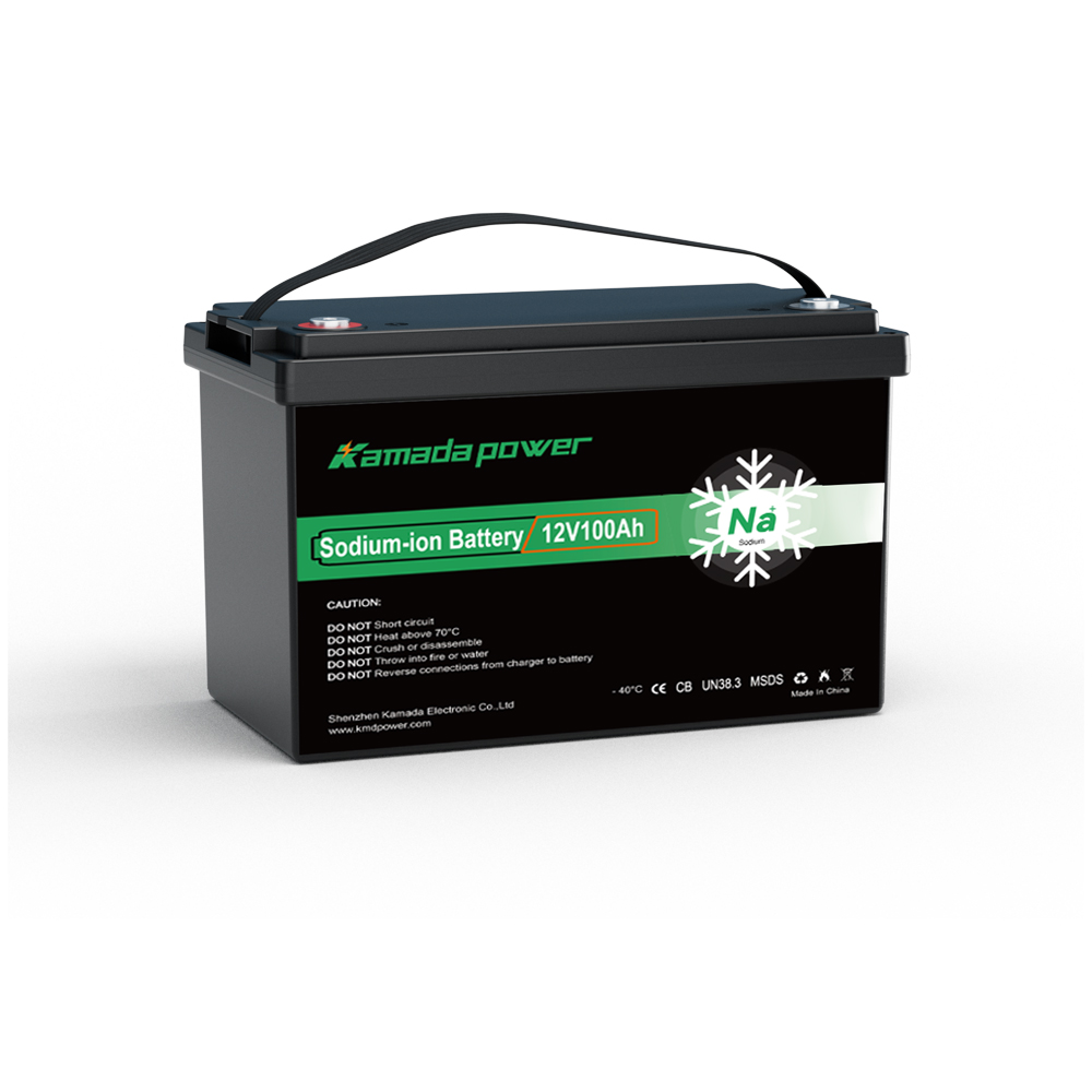
Batería de iones de sodio Kamada Power 12v 100Ah
Does “BMS Stops Charging” Mean the Battery Disconnects from Every Load?
No. A BMS may tell a compatible charger to stop, switch a charge path or isolate common battery terminals. Discharge may remain permitted—or not. The finished-pack circuit and wiring determine the result.
Texas Instruments’ Parallel Paths with the BQ76952 Battery Monitor Family (SLUA952) compares series-FET and separate charge/discharge paths, including MOSFET body-diode current. A CHG-off signal alone does not prove physical current blocking. These are circuit examples—not evidence of Kamada Power BMS topology. Camera uptime does not prove a safe, rated discharge path; unintended body-diode conduction needs separate review.
Victron’s Smart BMS 12-200 guide describes separate Charge disconnect y Load disconnect signals; these do not establish Kamada Power Sodium Battery pack functionality.
| Observed event | What changes electrically | Can CCTV keep running? |
|---|
| Charge permission removed through a supported controller input | MPPT is commanded to reduce or stop charging | Potentially yes, if permitted battery discharge and the camera supply remain available |
| CHG-path switch opens while discharge remains allowed | Current path changes according to actual FET/port circuit | Design-dependent; verify permitted current path, blocking, thermal limits and DC-bus response |
| Common pack output becomes isolated | Battery may stop supporting the shared DC bus | Not guaranteed without another approved source or power-path device |
| MPPT LOAD output or DC converter shuts off | Camera-facing supply is removed | No, unless a qualified backup maintains that rail |
Confirm the approved discharge path, CHG/DSG states and recovery through manufacturer documentation.
Where Are the Camera Loads Connected in the Battery–MPPT System?
Follow the actual wiring.
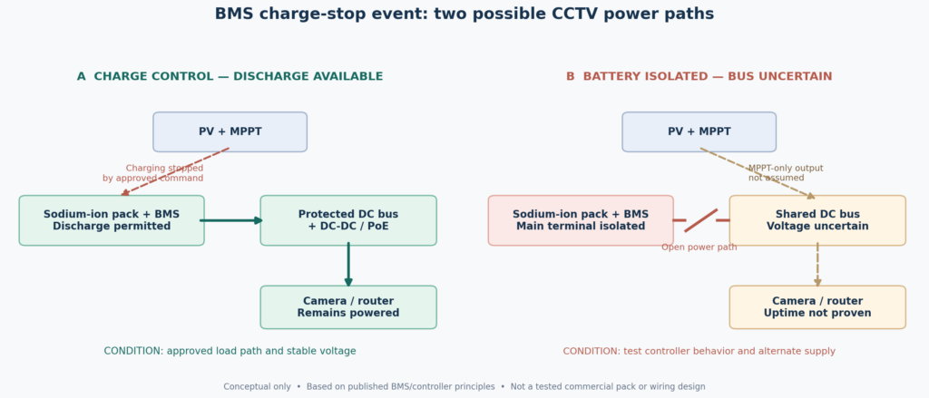
Architecture A — Charger control, battery-backed load. An approved BMS-to-MPPT interface commands charge stop while discharge stays enabled. Protected distribution feeds DC-DC/PoE converters. Recording may continue if the camera bus remains within limits. This architecture is unavailable if the actual pack and charger lack a supported control interface.
Architecture B — A common DC bus loses its battery reference. The pack isolates its main terminals while MPPT and camera converters remain on the bus. The controller may not support battery-absent loads; uninterrupted recording may require an approved alternate supply.
A. CHARGE INHIBIT                    B. PACK ISOLATION
PV → MPPT (charge disabled)          PV → MPPT (behavior unverified)
             │                                   │
     Battery discharge allowed           Battery terminals isolated
             │                                   ╳
     Protected DC distribution           Shared DC bus at risk
             │                                   │
       DC-DC / PoE → CCTV                 DC-DC / PoE → CCTV ?
Figure 1. Conceptual paths, not a Kamada Power schematic or tested installation.
Victron’s SmartSolar 100/30–100/50 installation manual specifies battery-before-PV connection for automatic voltage detection, with a documented manually configured exception. Its troubleshooting guide shows that a controller display or near-zero charge current cannot establish a healthy battery connection. Verify the physical bus under load.
Load control varies by model. Some controllers have physical LOAD terminals; Victron SmartSolar 100/30 and 100/50 do not. They can provide a virtual load-output signal via VE.Direct TX to a suitable external disconnect device, not power a camera directly from a LOAD terminal. Victron virtual-load documentation. Map the actual load switch, fuses and DC-DC/PoE connections.
Which Electrical Transients Matter When Charging Permission Changes?
A supported charger-disable command may ramp current down; internal switching or pack isolation may behave differently. Transients depend on controller, wiring, capacitance and load. “BMS shutdown” alone predicts neither amplitude nor camera uptime.
Zero charge current alone does not identify a BMS trip. Distinguish normal CC/CV taper or completion, PV shortage, an approved charger-inhibit command and an actual BMS protection event using time-aligned BMS and MPPT records. An inhibit command does not prove a CHG FET opened.
Synchronize these measurements:
- Battery voltage and signed branch current: Is the pack charging, discharging or disconnected?
- MPPT output and CCTV load-branch currents, plus camera-bus voltage: Where does power flow, and does the load remain within voltage limits?
- BMS/MPPT event records: Charge/discharge permission, fault states, MPPT mode and physical/virtual LOAD control.
- Service logs: PoE events, camera/NVR recording gaps, router connectivity and recovery time.
A modo de ejemplo, 24W of camera/router output at 90% assumed efficiency draws 24 ÷ (0.90 × 12.0) ≈ 2.22A at 12V. This is arithmetic, not pack test data; capture interruptions that average current readings miss.
En supplied Kamada Power 12V 100Ah Sodium ion Battery datasheet especifica 12V nominal, 1,200Wh nominal, 15.6V maximum charge voltage and 8V discharge cutoff. Its 0–45°C standard charging procedure is 20A CC to 15.6V, then CV to 2A. Other temperatures require revision-specific current approval. 15.6V is a charge target, not a documented BMS trip threshold; 8V is a protective cutoff, not a normal CCTV service target.
En Batería de iones de sodio Kamada Power 12v 100ah uses a 12.8V model label; do not merge unverified revisions. Neither source establishes independent CHG/DSG paths, a charger-control interface, trip/recovery thresholds or uninterrupted CCTV output. Without a confirmed interface, Architecture A is only a concept—not a supported pack feature.
How Can an OEM Test BMS–MPPT Coordination Without Unsafe Live Disconnection?
Do not pull live battery wiring, bypass fuses or deliberately force cell overvoltage/temperature protection during PV charging. Charger-disable and pack-isolation tests are distinct.
Use only an approved charger-control input. Internal FET switching or full isolation needs the pack maker’s authorized procedure and test fixture; otherwise record not verified.
1. Identify allowed states. Record pack/BMS revision, MPPT model, settings, interface polarity, wiring and CHG/DSG recovery. Obtain the maker’s permitted discharge-current paths and ratings during charge inhibit.
2. Establish a baseline. At allowed temperature and state of charge, record MPPT output, signed battery current, CCTV branch current/bus voltage, PoE events and recording.
3. Command approved charge inhibit. Confirm the MPPT follows the supported command and charging stops while permitted discharge maintains loads. This checks command behavior only, not FET isolation.
4. Capture the transition. Use rated isolated/differential instruments at pack and camera supply input. Record current direction, voltage transients, resets and video gaps; confirm the conducting path is approved for continuous current and heat. An online LED does not prove recording continuity.
5. Check recovery and energy balance. Resume charge only by the approved procedure. Record fault latching, repeated cycling, battery Wh restored and reserve over representative day/night cycles. Initial survival does not prove lasting uptime.
6. Separate other failures. Lost BMS communication, FET switching, pack isolation and PV loss need distinct manufacturer-approved tests. Mark untested states explicitly.
Set separate pass criteria for regulated power, continuous local recording and required remote video service. Synchronize footage timestamps with electrical events. A later reconnection does not erase a recording gap.
Which Pack–Controller Combinations Are Suitable for Unattended CCTV?
Decide what powers the cameras during charge inhibit and whether charging reliably resumes.
| Verified design finding | OEM approval or purchasing decision |
|---|
| Supported charger-disable command, approved discharge path and video/bus continuity verified | Qualify that specific pack–MPPT–load configuration for the tested state |
| BMS isolation removes the common pack output without a qualified alternate source | Redesign the power path or reject continuous-recording use |
| Controller opens a physical LOAD output or a virtual-load-controlled external switch | Check the actual output/relay logic and wiring, not battery Ah |
| Bus disturbance causes camera/NVR gaps despite continued nominal battery voltage | Improve qualified power-path regulation or continuity design |
| Charging cannot resume automatically or cycle-by-cycle energy reserve declines | Fix control/recovery and charging, not simply pack capacity |
| Pack BMS topology, voltage/current restrictions or recovery behavior lack documentation | Hold design approval until revision-specific evidence is supplied |
Approved parallel packs may add reserve; a healthy parallel pack may sustain the bus during one pack’s event only if the approved arrangement and current transfer pass testing. Common faults, charger mismatch and series wiring remain separate limits.
What Should an Integrator Request Before Sampling a Sodium-Ion Pack?
Request a pack power-path diagram or formal CHG/DSG state table, interface pinout and polarity, rated discharge paths, BMS revision, temperature-dependent charging limits, recovery states and supporting test records. Verify the MPPT supports the approved 15.6V CC/CV procedure or an explicitly authorized alternative. Do not infer BMS trip thresholds from charge voltage.
Provide MPPT firmware, DC schematic, PoE load, recording requirements, temperature and volume. Require two acceptance results: immediate camera continuity during approved charge inhibit, and reliable recharge with stable reserve over repeated cycles.
En Batería de iones de sodio Kamada Power 12v 100ah y security-system guide offer product context—not evidence this MPPT/pack pairing has passed.
Preguntas frecuentes
If a sodium-ion BMS disables charging, will the cameras shut off?
Not necessarily. If discharge stays enabled and the DC bus remains within limits, recording may continue. A pack-output or controller-controlled load shutdown can interrupt it. Immediate continuity does not prove charge recovery.
Does a sodium-ion pack automatically have separate charging and discharging MOSFETs?
No. Chemistry and nominal voltage do not reveal FET topology. CHG/DSG control signals alone cannot prove current blocking. Check the pack’s complete circuit and protection-state definitions.
Can the MPPT alone keep CCTV running if the battery disconnects in sunlight?
Do not assume so. Some controllers display voltage while disconnected. Verify documented battery-absent behavior and any alternate supply; never disconnect a live battery to find out.
Is this the same problem as a low-voltage disconnect before the battery is empty?
No. Early LVD removes a load at a voltage threshold. Here the initiating event is charge inhibition or pack isolation during charging. The diagnosis and remedy differ.
Would two approved parallel 100Ah packs prevent a camera reboot during charge cutoff?
Not necessarily. In a manufacturer-approved parallel arrangement, another healthy pack may maintain the DC bus during an individual-pack event. Verify current redistribution, independent and common protection, transients, charger response and unattended restart; continuity is not guaranteed.
Conclusión
Charge inhibition does not automatically interrupt CCTV recording. An approved charger command may preserve discharge; internal CHG switching or pack isolation may not. Continued power alone does not validate the safety of its current path. The supplied Batería de iones de sodio Kamada Power 12V 100Ah sheet gives 15.6V standard charging and an 8V protective discharge cutoff, but not a verified BMS control interface or recovery method. Qualify the exact pack–MPPT–DC-bus system for immediate footage continuity and reliable recharging before deployment. Contacto Kamada Power with your controller, schematic, camera loads, temperatures and projected annual volume for a revision-specific review.