A remote CCTV site stops recording before dawn. The solar PoE switch reports low-battery shutdown, but the sodium-ion battery pack has not entered BMS undervoltage protection. Is the battery undersized, or has the switch removed the load early? A solar PoE switch can disconnect cameras before the pack reaches its discharge limit, but a voltage reading cannot quantify the remaining usable energy. Compare LVD, load-reconnect voltage (LVR), approved pack limits and voltage under the real camera load.
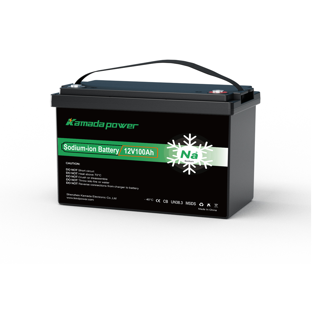
Kamada Power 12v 100Ah Sodium ion Battery
Can a Solar PoE Switch Shut Down Before the Battery BMS Does?
Yes. Many solar PoE controllers manage the camera load separately from the battery’s internal protection. The controller may switch off its PoE or DC load output when its measured battery-input voltage reaches a programmed threshold. The BMS may still permit discharge at that moment. That is not necessarily a controller fault: LVD is designed to preserve battery reserve, avoid damaging discharge, and give the system a defined recovery point.
The architecture matters. An integrated solar PoE unit may switch off its PoE output. A separate MPPT may instead command an external relay, while a battery-connected injector may ignore its load-control signal. Also check timed and daylight-dependent operating modes. Identify what actually interrupts camera power before blaming the battery.
The Linovision POE-SW804G-SOLAR manual documents an over-discharge protection function that turns off the load output. Its reference 12V LiFePO4 profile lists 11.2V for over-discharge and 12.3V for recovery. These are equipment-specific reference settings for that battery profile, not sodium-ion recommendations. The exact firmware configuration and operating behavior must be verified in an actual project.
What Do Published LVD and Reconnect Settings Tell Us?
Different controllers—and different modes in one controller—use substantially different thresholds. The following are verifiable examples of published equipment settings, not suggested settings for a sodium-ion battery.
| Manufacturer and documented mode | 12V load disconnect | 12V load reconnect | Important limitation |
|---|
| Linovision POE-SW804G-SOLAR, reference 4S LiFePO4 profile | 11.2V | 12.3V | Confirm the actual configuration and load-control implementation |
| Victron SmartSolar, conventional load algorithm 2 | 11.8V | 14.0V | Controls a load-output function or external disconnect device, depending on model |
| Morningstar GenStar MPPT, LiFePO4 preset 5 | 12.5V | 13.15V | One-minute LVD warning; 0mV/A current compensation; not a sodium-ion preset |
Sources: Linovision controller manual, Victron SmartSolar load-output settings, and Morningstar GenStar load-control documentation. Compare only the designated models and modes; these numbers are not interchangeable.
Figure 1 — Published 12V Controller LVD and LVR Thresholds
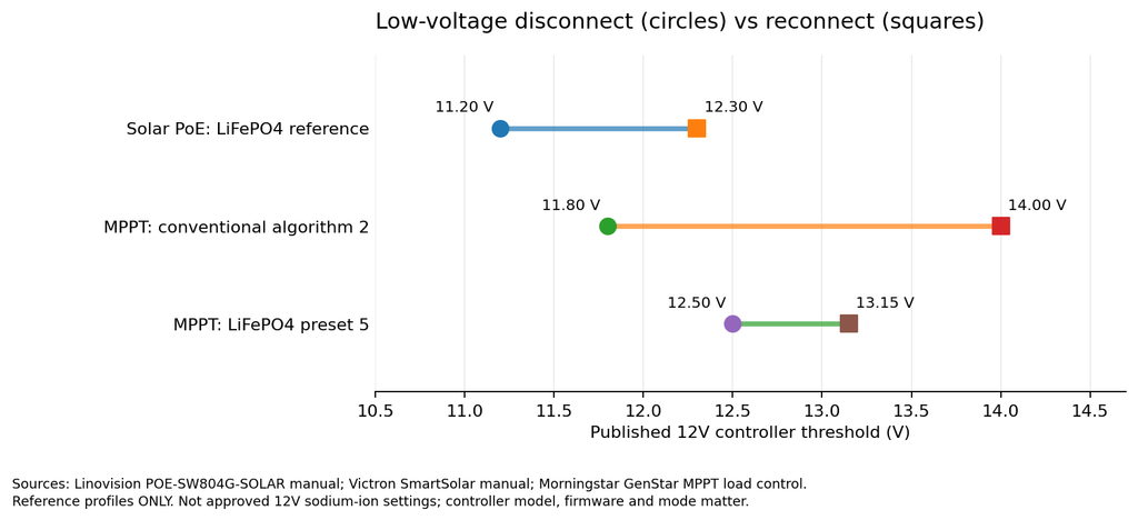
Published low-voltage disconnect and reconnect settings for selected Linovision, Victron, and Morningstar controller modes. These are manufacturer reference settings, not recommended LVD/LVR values for Kamada Power sodium-ion battery.
Reconnect voltage can sit well above disconnect voltage. This hysteresis limits cycling, but may leave a site offline after sunrise. A rebound in unloaded battery voltage does not establish sufficient energy for sustained restart.
Does the 12V Sodium-Ion Pack Still Have Usable Energy at LVD?
Possibly, but not simply because the BMS has not tripped. The supplied KMDPOWER 12V 100Ah datasheet specifies 12V nominal, 100Ah, 1,200Wh nominal energy, 15.6V maximum charging voltage, and 8V discharge cutoff. The 8V value is a protective endpoint, not a recommended solar PoE LVD or proof of usable Wh below the controller threshold. The Kamada Power 12v 100ah Sodium ion Battery uses a 12.8V model label; do not merge revisions without confirmation. Obtain loaded-discharge data, BMS settings, and temperature limits. Voltage alone cannot quantify remaining energy.
Battery terminal voltage is influenced by state of charge, load current, temperature, and internal resistance. The PoE controller also sees wiring and connector losses. During a high load, the controller’s measured voltage can cross its LVD while the voltage at the pack terminals remains higher.
For illustration, 5A × 0.04Ω = 0.20V drop. The controller could read 11.2V while the battery reads 11.4V. This is hypothetical, not a KMDPOWER test. The Linovision 12V unit specifies a 60W PoE budget and 5A maximum load output; check both limits and the cameras’ peak power, not just average watts. Actual 5A demand must also respect all device and output ratings. Linovision specifications.
To quantify energy withheld by LVD, compare approved discharge tests from the same initial battery condition, at matched load and temperature, with solar charging disabled or separately metered:
Battery-side energy delivered before LVD (Wh) = ∫ battery-terminal voltage × net battery discharge current dt, up to the first LVD event.
A separate approved discharge test can establish additional energy within the pack’s permitted limits. Compare battery-side Wh on the same basis, and meter PoE load-side Wh separately to capture conversion and wiring losses. The difference is energy unavailable under that tested controller configuration, not a fixed percentage of 1,200Wh. Never bypass the BMS.
Why the BMS cutoff is not a useful everyday LVD target
A BMS undervoltage trip is a last-resort protection boundary, not a normal surveillance shutdown target. The supplied pack’s 8V discharge cutoff is not an instruction to lower controller LVD to 8V. Allow verified margins for voltage sag, converter minimum input, temperature and reserve; otherwise abrupt outages and repeated resets may follow. There is no universal 12V sodium-ion LVD value.
Why Might the Cameras Stay Offline After Solar Charging Returns?
The controller disconnects at LVD and may wait for LVR, a delay or another condition before reconnecting. The Victron SmartSolar manual specifies a two-minute response delay for certain load algorithms. Morningstar documents warnings and current compensation, but its LiFePO4 preset 5 has 0mV/A compensation. A scheduled or light-controlled OFF state is another possible explanation for missing video.
The relevant event chain is:
Battery supplies cameras → controller reaches LVD → camera load disconnects → solar charging raises battery voltage → controller reaches LVR → cameras attempt to restart.
If voltage falls again when the PoE switch and cameras start, the load may disconnect once more. That symptom needs a restart-under-load test—not an assumption that the battery is depleted. Keep this investigation limited to LVD and reconnect coordination; failure of an MPPT to power up after BMS isolation is a different diagnostic problem.
How Should an OEM Test LVD Without Defeating Battery Protection?
Use the actual PoE switch, firmware, pack revision, charger, fuses, wiring and camera load. First verify charging compatibility: the KMDPOWER datasheet gives a 15.6V maximum charge voltage, while Linovision’s reference LiFePO4 profile specifies 14.4V charging, 15.0V overvoltage protection and 0°C low-temperature charge protection. Its charging limit is 10A. These are not approved sodium-ion settings; confirm programmable limits, battery-approved charge profile and temperature behavior with both manufacturers before testing. A bench supply alone cannot prove pack runtime.
Step 1 — Identify all voltage limits. Record LVD/LVR, sensing point, tolerances, delays and load schedule. Verify the 15.6V charge limit, approved current-versus-temperature charging rules, pack BMS settings and converter minimum input. The datasheet’s standard 15.6V CC/CV procedure is stated for 0–45°C; clarify charging controls outside that band before qualification.
Step 2 — Record voltage at two locations. Log battery terminals and controller input under the real PoE load, alongside net battery current, temperature, controller mode, PoE output power and camera availability. Include IR, heaters and startup demand. Note the first interruption and whether it is LVD, a load schedule or a power-budget trip. AXIS power-consumption guidance.
Step 3 — Use an approved controlled-discharge procedure. Start from a documented initial battery condition. Keep the load and temperature controlled. Stop at the first applicable system limit. Do not short, bypass, manually force a BMS trip, or continue outside the approved discharge envelope.
Step 4 — Check the remaining-energy hypothesis. Under an approved test plan, compare battery-side Wh and camera-side Wh at matched load, temperature and starting condition. Account for solar input; a post-disconnect voltage reading is not a capacity test. Stop before any equipment or battery limit is exceeded.
Step 5 — Verify recovery. Restore the approved charging source. Capture the controller’s reconnect point and the camera startup transient. Repeat at the project’s relevant temperature and after realistic cable and connector losses have been included.
The record should distinguish controller LVD, scheduled/daylight load-off, PoE power-budget or converter undervoltage, BMS protection, and insufficient available energy. They call for different corrections.
Should the OEM Change the PoE Switch, Its Settings, or the Battery?
The purchase decision depends on the verified cause—not on a preference for sodium-ion, LiFePO4, or any other chemistry.
| Test outcome | Appropriate next decision |
|---|
| Controller LVD occurs early; a manufacturer-approved profile remains within all limits | Qualify settings with measured reserve and restart margin |
| LVD/LVR or charging profile is incompatible with the exact pack | Choose a compatible controller or protected power architecture; do not import LiFePO4 defaults |
| PoE power budget is exceeded, or converter input voltage fails first | Correct the load/power interface; extra battery Ah is not the first remedy |
| BMS discharge protection operates first, or the measured pack cannot meet required reserve | Reassess the exact pack, current/temperature limits, usable Wh, and system energy needs |
| Site fails at reconnection or is disabled by schedule/light mode | Verify hysteresis, startup surge, voltage drop and load-control mode |
Manufacturer-approved parallel expansion can add energy and reduce per-pack load, potentially reducing voltage sag. It does not change nominal bank voltage or fix an incompatible LVD setting or charge profile. A larger bank also does not increase solar charging current. Recalculate measured Wh and recharge time before adding packs.
An OEM decision record needs switch firmware, charging settings, LVD/LVR, pack revision, measured Wh, load budget and restart reserve. For wider context see Kamada Power 12V security-system applications; here the question is whether the controller makes the pack’s usable energy available to the cameras.
FAQs
Can a solar PoE switch disconnect while the BMS still permits discharge?
Yes. A controller’s own LVD can remove the camera load before the pack enters BMS undervoltage protection. Whether meaningful additional Wh remains must be measured under approved conditions.
Does a higher battery voltage after shutdown prove the battery was not empty?
No. Voltage can rebound when load is removed. Without the discharge curve, current, temperature, and controller event record, the reading does not establish remaining usable energy.
Can I simply lower LVD to the battery BMS cutoff voltage?
No. The supplied Kamada Power datasheet’s 8V discharge cutoff is not a recommended LVD. Use the exact pack and equipment limits with a tested margin for voltage sag, converter minimum input and recovery.
Why does the camera not restart as soon as the sun rises?
The controller may require a higher reconnect voltage, a delay, or other conditions. Solar energy might also be insufficient to sustain camera startup after reconnection. Measure both voltage and current during recovery.
Will adding another 100Ah battery fix early LVD?
Not necessarily. Approved parallel packs add energy and may reduce voltage sag, but the LVD and charger settings still apply. Verify threshold compatibility and charging capacity before expanding.
Conclusion
A solar PoE switch can disconnect CCTV loads before a sodium-ion pack reaches its BMS protection boundary. The energy left inaccessible depends on measured Wh, LVD/LVR, load budget, wiring loss and restart—not the 8V cutoff or nominal 1,200Wh alone. First verify charging compatibility, especially the 15.6V pack limit against the controller’s programmable range and temperature protections. For a Kamada Power 12V 100Ah sodium-ion battery, contact Kamada Power with the PoE model, charge/LVD/LVR settings, load, temperatures and expected volume. Request a revision-specific compatibility test plan before purchasing.